Knowledgebase


Fault Current Calculations at Source Component
Hello again, from Modecsoft Knowledgebase. This time we will be looking at fault current calculations of our Three-Phase Source component. This article will be for User Defined Source and Transformer options only.
Note: Transformer option of a single-phase source component is no different than the User Defined Source option.
Now, let us explore the initial settings for both options:
> User defined source option expects the user to provide the power, S in kVA, and per cent impedance, %Z, of the transformer only.
> Transformer option, on the other hand, additionally requires primary fault level in MVA, and primary voltage in kV.
Once required fields are filled in, the rest will be calculated by ElectricalOM as you hit the Calculate fault button. By saying “the rest” I mean, Prospective Short Circuit Current (symmetrical fault), Prospective Earth Fault Current, respective impedances, Zpscc and Zpefc (Ze), and respective power factors.
The difference will be clear in a bit, but before we carry on to calculations, let us look at some definitions:
Prospective Short Circuit Current or PSCC is the maximum current which will flow through the line and the neutral conductors of a single-phase circuit, or through line conductors of a three-phase circuit.
Prospective Earth Fault Current or PEFC is the maximum current which will flow through the line and earth conductors of a circuit, single-phase or three-phase.
The highest value, PSCC or PEFC, is then taken as Prospective Fault Current or PFC and it is used to calculate disconnection times, to check the breaking capacity of protective devices, etc.
As a note, unless we have a TT or a TN-S system, PSCC and PEFC will be very close to each other for a single-phase system, since the fault path for PSCC and PEFC is almost the same. I said almost, because the cross section of cpc is generally smaller than the neutral conductor, and this changes the impedance of the path slightly (PSCC will be higher than PEFC).
If you are dealing with a three-phase TN-C-S system, and you only know the PEFC, as a rule of thumb, you can multiply this by 2 or 1.732 (Sqrt(3)) and use this value as your PSCC.
f factor is the ratio of downstream (to the fault) impedance to upstream (to the fault) impedance, and it is used to calculate the M multiplier for the case where we know the fault level upstream.
M multiplier is to be used against the value of the fault current in the immediate fault point, and it is essentially the ratio of upstream (to the fault) impedance to total impedance.
Now, back to ElectricalOM…
ElectricalOM lets users to type in their own values for fault currents and impedances, if known and calculation is not required. However, you can only define either the fault current or the impedance. As you type in one of these values, the other one will be calculated for you.
If you define a fault current (or impedance), you should not use the Calculate fault button because this will override your values, however, you still need to use the Calculate fault power factor button to calculate the power factor during the fault conditions for your values.
And the last thing about ElectricalOM’s supply component: Fault currents calculated here are at the terminals of the secondary side of the transformer, so, no conductor impedances are at play.
There are various ways to calculate fault currents, but since ElectricalOM is not a simulation software, it follows a steady state approach and does not deal with transient situations.
ElectricalOM also has a motor contribution calculation, but this will be discussed in a different article and not in this one.
Now it is time to dive into calculations and see the difference between our User Defined Source and Transformer options.
If you want to go deeper in this subject, then, I encourage you to have a look at IEC 60909.
One way to calculate fault currents is to assume the source has no internal impedance and has an infinite capacity so it can feed the fault indefinitely until a protective device opens the circuit. This is called Infinite Bus Theory and it represents a worst-case scenario.
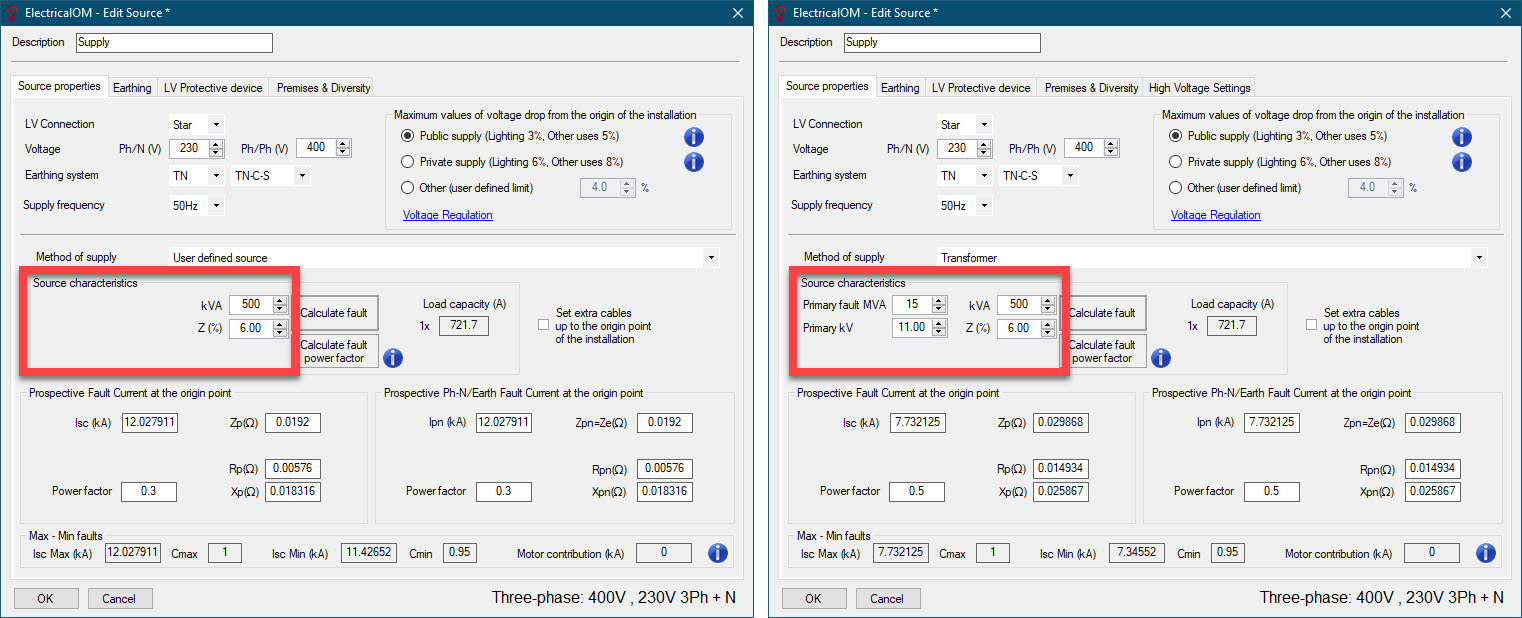
User Defined Source option
Now, we will consider a 500kVA transformer with 6% impedance. These are all we need for our User Defined Source option.
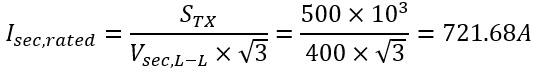
Here, I will give a break and try to describe %Z, very briefly.
Let us assume we short our transformer’s secondary terminals and start applying voltage to the primary side. When we read the rated current at the secondary side, we record the voltage at the primary. The ratio of this voltage and the primary rated voltage is essentially the %Z.
The ratio (which is %Z), shall also be the same at the secondary. Furthermore, this is not only true for voltages but also currents, only inversely.
So, we can write:
where;
%Z : Per cent impedance
Vpri,rated : Primary rated voltage of the transformer
Vpri,PSCC : Primary voltage of the transformer when secondary terminals are shorted
Vsec,rated : Secondary rated voltage of the transformer
Vsec,PSCC : Secondary voltage of the transformer when secondary terminals are shorted
Ipri,rated : Primary rated current of the transformer
Ipri,PSCC : Primary current of the transformer when secondary terminals are shorted
Isec,rated : Secondary rated current of the transformer
Isec,PSCC : Secondary current of the transformer when secondary terminals are shorted
Now back to ElectricalOM calculations…
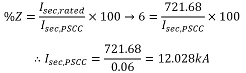
First, we calculate the full load current (rated current) of the transformer at the secondary side. ElectricalOM call it Load capacity (see picture):
 In some sources, you may see an M multiplier. This is given by:
Then, PSCC is calculated using the formula below:
![]()
This is the same thing; however, directly calculating the M multiplier and multiplying it by the rated current makes things a bit easier.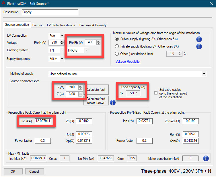
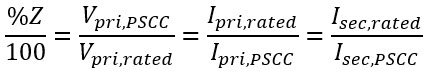
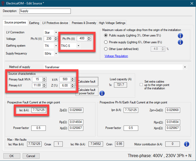
Transformer option
This time, we will use the Transformer option of ElectricalOM and calculate the prospective short circuit current again. I will also increase the decimals just to match the results to ElectricalOM.
Required transformer data is like User Defined Source but additionally, we need to fill in the Primary fault MVA and Primary kV fields too. This option is to be used when we are aware of the fault level at the transformer primary.
First, we will calculate the fault current at the primary side (rather than the rated current at the secondary side) and refer it to the secondary side after some conditioning. Primary fault current is calculated as follows: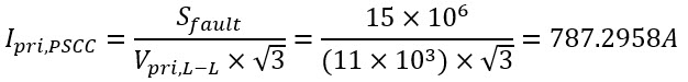
where;
Ipri,PSCC : Primary current of the transformer when secondary terminals are shorted
Sfault : Fault level in VA
Vpri,L-L : Primary line-to-line voltage
Now we are supposed to calculate M multiplier, however, we cannot calculate this directly this time since we have some impedance in between our transformer and an upstream transformer. That is how we are aware of the fault level, because supposedly somebody calculated a fault current at the secondary side of an upstream transformer and let us know. You may think this situation like a case where we have the previous transformer upstream to this one. (I will ignore the fact that we have 11kV as primary voltage and the previous transformer’s secondary was at 400V for the moment. I just want you to understand the concept.) Above, we calculated a secondary side fault current for the previous case, which can be imagined as the fault level for this case.
So, instead, we will calculate a factor called f first, using the formula below, and then, we will carry on calculating our M multiplier (We will not investigate the details of f here.) for the case where we know the upstream fault level:

Ipri,PSCC : Primary current of the transformer when secondary terminals are shorted
Vpri,L-L : Primary line-to-line voltage
%Z : Per cent impedance
STX : Power of transformer
Now, the M multiplier. The formula is given as below:![]()
Using M and primary PSCC, we will calculate the PSCC at the secondary side:

I hope this clarifies any questions you may have had in mind about ElectricalOM fault current calculations at supply point.
If you need further information, please feel free to:
> use our online manual, Getting Started (electricalom.com),
> visit our YouTube training channel, ElectricalOM - Learning and Training,
> post on our forum, ElectricalOM Forum,
> chat with us at our online chat, or
> contact us at support@modecsoft.com
Also Read
-
Exploring PD CLC/TR 50480:2011 and the UK National Annex NA: Additional Earth Conductors and Steel Armour in Parallel (Views: 1796)
-
Schneider Powerpact MCCB (Views: 3300)
-
Max Zs Calculation (Views: 52958)
-
Selectivity Study (Views: 15532)
-
Understanding the Integration of Arc Fault Detection Devices (AFDD) for Compliance in Certification and Reports to BS7671 (Views: 4662)
About Us
Modecsoft ElectricalOM is a Powerful, Fast & Accurate Software for Low Voltage Electrical Design, Modeling and Certification. Calculations and Checks Compliance with BS 7671:2018 and IEC 60364


Testimonials

Copyright © 2026 MODECSOFT Ltd. All Rights Reserved.
Privacy Policy Terms and Conditions Purchase and Refund Policy Software License Technical Support Policy