Schematic Module Side Panel
Schematic Module Side Panel is where the user can see various details about a selected circuit or item, and also can modify some of the settings. The side panel has four main tabs located on top of the screen, Properties, Symbols, Load sums, ad Volt drop.
- Properties: This tab is divided into two sections: board data and circuit data. Board data section is reserved for the distribution board's details. Even if the user selects a final circuit, ElectrcialOM will still display the corresponding (the circuit feeding the selected final circuit) distribution board details, but, if a distribution node other than a DB is selected, board data section will not be shown.
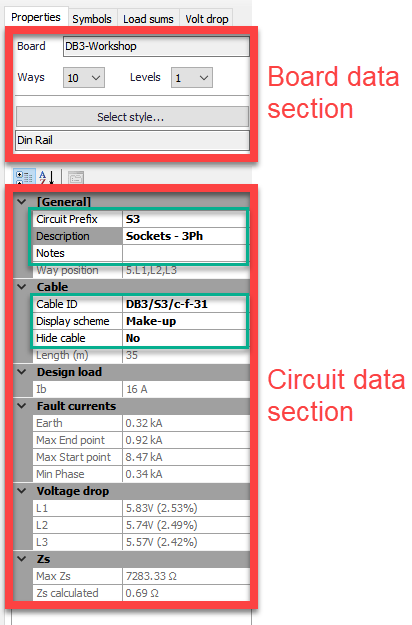
- Board Data Section: The user can modify the Board's number of ways, number of levels, and visual representation style of the board by using the Ways and Levels drop down lists, and Select style... button. If the user attempt to change the number of ways or levels, ElectricalOM will ask the user to approve with a message window.
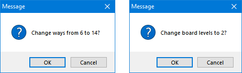
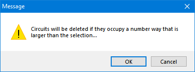
If the number of ways are being set to a lower value than they are already set, then, ElectricalOM will warn the user before proceeding and if the user clicks on OK will remove the higher numbered ways from the board.
For more details about changing number of ways of a distribution board please refer to Distribution Board section.
Board representation style can be changed by using the Select style... button. There are 5 styles available as shown below:

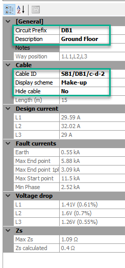
- Circuit Data Section: Below Board data section, Circuit data section is located where General, Cable, Circuit, Design current, Display options, Fault currents, Voltage drop, and Zs data are displayed under related titles.
Some of these can be modified directly from here by the user like the ones marked with green rectangles below, but some of them are based on calculations and for information only, and cannot be modified directly from schematic module side panel. There are greyed out to indicate that they are not user defined.
Display scheme and Hide cable data fields are drop down lists where others are text fields where the user may type required data. For Circuit Prefix, Description, and Notes, see Circuit Edit Module Tab section. For Cable ID, Display scheme, see Other details Tab section, and for Hide cable, see Conductor Tab in Circuit Details Module section.
Display Options section is also consist of many drop down lists and they are used to display or hide certain information about the selected circuit.
- Symbols: Please refer to Symbols Tab section.
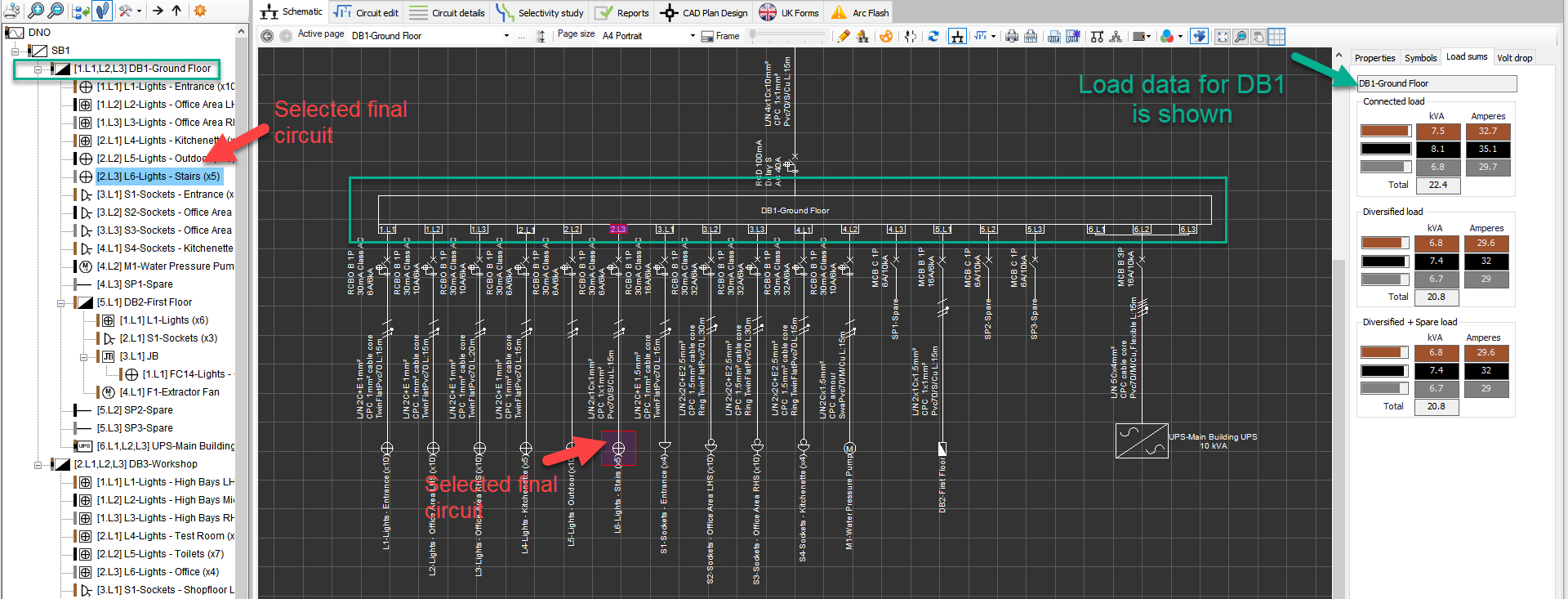
- Load sums: This tab will display load data of the related distribution node of a selected circuit. So, if a final circuit is selected, this tab will still display the load data of the distribution node of the selected final circuit.
- Volt drop: This tab displays voltage drop data of the selected circuit. Colour coded fields, represent each phase, displays the voltage drop in Volts and next to these ElectrcialOM also displays the voltage drop in percentage.
- Supply (A) section will display associated distribution circuit's voltage drop from the origin to the feeding point of the selected circuit,
- Circuit (B) displays the selected circuit's voltage drop after the distribution circuit which id from the feeding point to the end point of the selected circuit, and
- Total (A+B) displays the total voltage drop associated with the selected circuit from the origin to the end point. The maximum percentage value will change according to the circuit type and voltage drop settings. See Voltage Drop Tab and Source.
- Conductor energy loss (kW) displays the energy loss of the conductor used for that circuit at operating and maximum temperature.