Conductor Tab
Conductor tab will list the circuits displaying conductors and various information related with the conductors connected to the selected node.
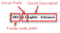
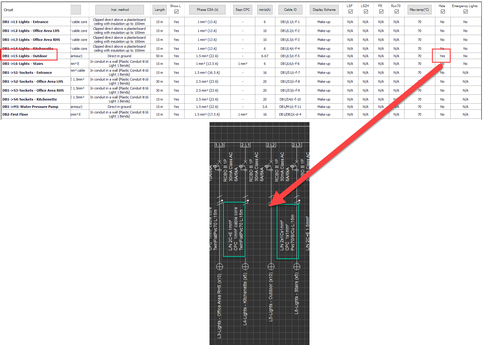
- Circuit: This column displays the circuits' description including the feeder nodes' prefixes.
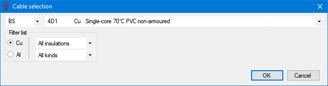
- Conductor: This column displays the conductor/cable type and cross-section information of a circuit. The title button can be used to modify the conductor/cable type but not the cross-section. The dialogue window is similar to the Circuit edit module's Ph/N Conductor tab.

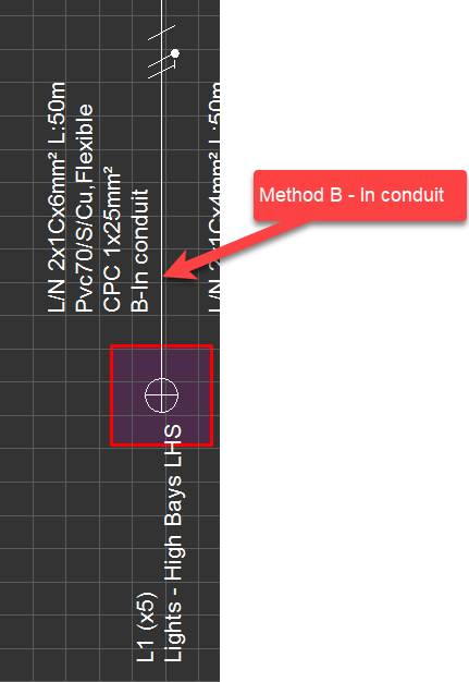
- Inst. method: This column displays the installation method of the conductor/cable of a circuit. The title button can be used to modify the method and the dialogue window is similar to the Circuit edit module's Ph/N Conductor tab.
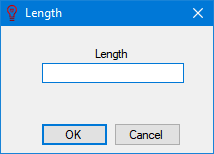
- Length: This column displays the length of the conductor/cable of a circuit. The user can type in required value in to the text field at the opening dialogue window once the title button is clicked.
- Show L tick box: This column will enables or disables the length data which can be displayed on schematics. The tick box under the title has an effect on the selected row only but not on the whole column, so, in order to modify multiple items, the user needs to select those items first.
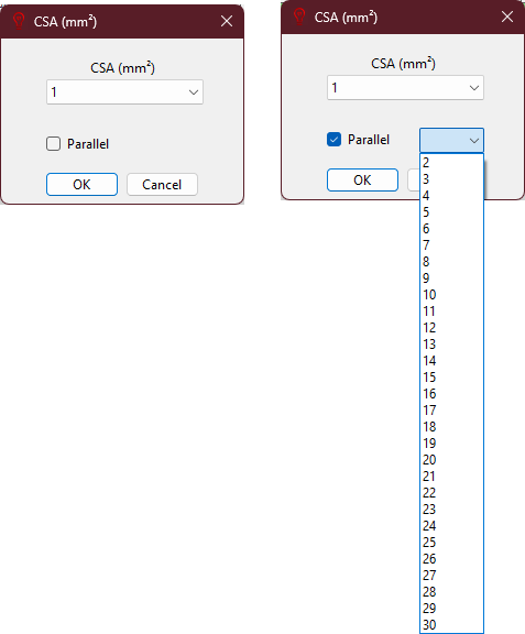
- Phase CSA (It) and Sepr. CPC: These columns display cross-section areas of the live and protective conductors of a circuit. Title buttons can be used to modify cross-section areas of selected circuit's conductors.
- Phase CSA (It) column also displays the It value of selected cable. Using parallel tick box, user can define parallel conductors. When this box is ticked, a new drop-down list will be visible to select number of parallel conductors.
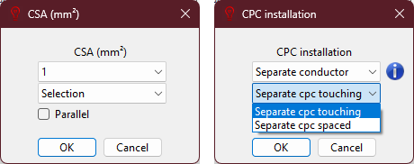
- Sepr. CPC window has two drop-down lists.First one is used to directly define a cross-section for the cpc. Second list is used to automatically calculate a csa. After selecting an option ElectricalOM will calculate the value and update the cpc cross-section for selected circuits. Similar to Phase CSA (It) option, using parallel tick box, user can define parallel conductors.Sepr. CPC column will work only if a separate circuit protective conductor is defined at the Circuit edit module's Earthing tab. and if not, selecting any option from Sepr. CPC list will not have any effect.
- minIz(A): This column will display the minimum effective capacity of the phase conductor and this cannot be modified by the user. This is also shown on Circuit edit module's Calculation Section.
- CableID: This column displays the ID of the cable of a circuit. The user may modify the value by clicking on the title button. For more details about the cable identification, please refer to Auto Cable ID numbering... option at Functions menu and Circuit edit module's Other details tab.
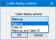
- Display scheme: The display scheme of cables can be modified using the title button of this column. More details can be found under title Predefine Cable Display Scheme at Project info and options... Menu and at Circuit edit module's Other details tab.
- LSF/LSZH/FR/Run70 tick boxes: These will define if a cable is a Low Smoke & Fume, Low Smoke Zero Halogen or a Fire rated/resistant cable. Run70 will set the selected cable(s) to be calculated as it will run up to 70°C rather than any other higher value which may have been defined by the type of the cable (e.g. an XLPE insulated cable may be run up to 90°C.). The tick box will have effect on only the selected rows but not on the whole column.
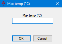
- Max. temp (°C): This column displays the set maximum temperature, see Ph/N Conductor tab.
- Hide tick box: If this box is ticked, then, the data related with selected cable(s) will be hidden on the schematics.
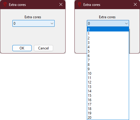
- Extra Cores: This option used to define extra cores within the cable of there are any. Number of cores can be selected using the drop-down list. This displays and updates the information set at Circuit Edit Tab's Ph/N Conductor.
- Show meth: This will display the installation method of the selected cable on schematic.
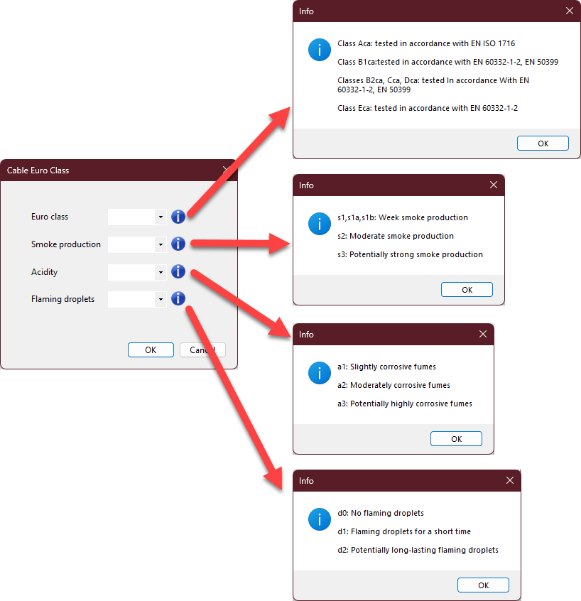
- Cable class: This option displays and updates cable classification of Circuit Edit Tab, Other, Cable Classification section.