Circuit Edit Module Tab
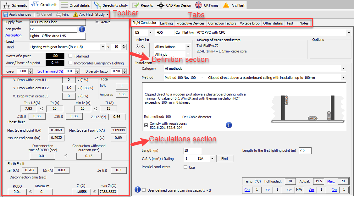
Circuit Edit Module is the most important and the main module of ElectrcialOM. where users define and set most of the system variables and component properties. The module window consists of a toolbar, sub module tabs, definition section, and calculations section. After adding a new circuit via the system tree area, or inserting a new circuit by using the Insert Menu, the Circuit Edit Module will display data related with the selected circuit.
Toolbar consists of
- Apply changes button which will apply the changes and updates the warning section.
- Cancel button reverts the last action.
- Print button initiates the print window.
- Arc Flash Study drop-down list is used for arc flash studies. Please refer to Arc Flash Study add-on user manual.
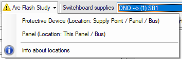
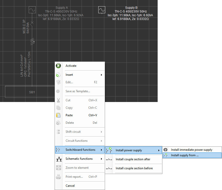
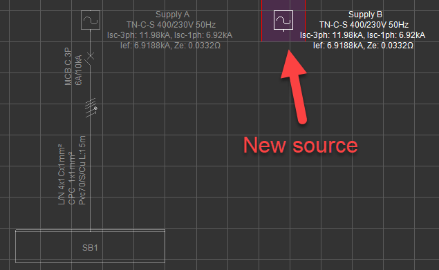
- Switchboard supplies drop-down list lists all supplies available to the selected switchboard. This option is available only for switchboards fed by multiple sources. Using the drop-down list, user can switch between each source available. Calculations related with the selected source will be displayed.
Definition Section, is reserved for user defined data. This section will differ depending on the circuit type; distribution circuit or final circuit.
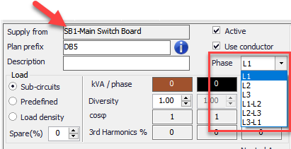
- Supply from field will be automatically filled in by ElectricalOM and cannot be changed by the user.
- Active tick box, will set the circuit to be active or will set the circuit to be passive, which means the circuit will still be shown but will not affect the system in any way.
- Use conductor tick box will leave or remove the feeder cable. If this box is unticked, ElectrciaOM will remove the cable between the selected point and the feeder point.
- Plan prefix is reserved to assign a prefix for the circuits however there is no restriction of usage.
- Description is reserved to provide a short description of the circuit but again there is no restriction of usage. Final circuits will have a link where various properties of the selected circuit can be displayed on schematic.
- Phase (Only for 1ph components fed from a 3Ph switchboards) is used to chance the connection of single phase circuits fed from a three phase switch board. The user may choose to connect a single phase component as a Ph-N (L1, L2, or L3) or Ph-Ph (L1-L2, L1-L3, or L2-L3) connection by using this drop down list. ElectricalOM will automatically relevant parameters if a component is connected between two phases.
- Cable ID displays the cable tag for the selected circuit. It can be filled manually or can be automated. Please refer to Auto Cable ID and Auto BTS section numbering.
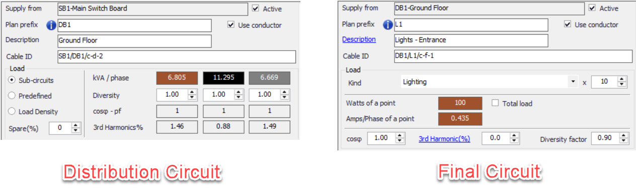
Load section is also differs depending on the selected circuit.
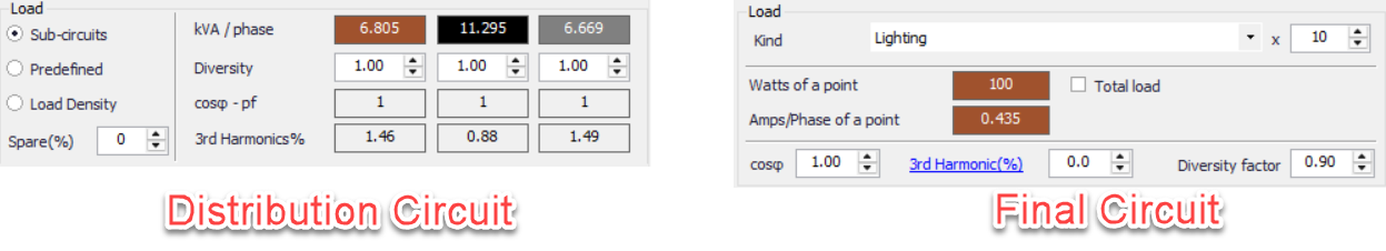
- Distribution Circuit
- Sub-circuits/Predefined/Load density selection buttons defines how the power of the distribution circuit will be calculated by ElectrcialOM.
- Sub-circuits option will consider individual circuits' data to calculate the total power. Right pane of the Load section will display total KVA/phase, diversity multiplier per phase, and power factor per phase of the selected distribution circuit. Only the diversity multiplier can be modified by the user, and others will be automatically calculated using data from connected circuits by ElectricalOM. The diversity setting here will have an effect on the distribution node meaning the total load of the selected distribution node will be multiplied by this diversity multiplier. Also see Apply board diversity to the upstream board in Functions Menu section.
- Predefined option will ignore any connected circuits, if any, and use the user defined current value to calculate the total power of the distribution node.
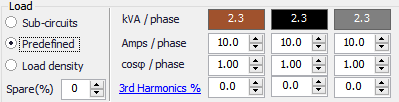
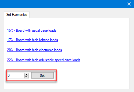
If Predefined option is selected, 3rd Harmonics % and cosφ fields will also be activated, so, the user can define any 3rd harmonics or power factor per phase for the selected distribution node. ElectricalOM will consider these values while calculating power, cable size, etc. Clicking on the 3rd Harmonics % hyperlink will bring up a short informative window to help the user to define a value. Any hyperlink selected from this window will automatically set the defined percentage, or the user may define any value using the text field at the bottom and clicking on Set button.
- Load density option will let the user to use predefined load density values from various bodies. When this option is selected only the diversity multiplier option will be enabled fore the user to modify and the rest of the data will be pulled from the Load density tab selection. Load density option is not available for Busbar Trunking System component. Please refer to Load Density Tab for more details.
- Spare(%) will tell ElectricalOM to leave a set percentage of the total load as a spare and do the calculations and checks accordingly taking into account the spare load set.
- KVA/phase: This row of values will display the power connected to each phase and cannot be changed by the user. The values are calculated by the data available from the connected circuits and data from other fields like Diversity, cosφ, and Spare (%).
- Amps/phase: This option will only be visible if Predefined is selected as load type. It allows the user to define a current value for each phase so a power value (KVA/phase) can be calculated.
- Diversity: User can define a diversity multiplier of each phase using this text fields. This option is not available if Predefined is selected as load type.
- cosφ/phase and 3rd Harmonics: These fields are used to define a power factor and a 3rd harmonic component percentage to each phase of the selected distribution circuit. They are only available if Predefined is selected as load type.
- Final Circuit
Load section of a final circuit has two data fields; Kind and x. Kind defines the circuit type and will affect various calculations, for example, diversity calculations. Also, some of the kinds have specific checks and additional settings. So, it is important to select an appropriate circuit type depending on the load characteristics. A brief description of circuit kinds having special features are listed below:
|
Lighting |
In-rush Current tab is available for in-rush current parameters. |
|
Lighting with gear losses (Ib x 1.8) |
|
|
Socket-outlet ring circuits |
Conductor and protective device sizing is altered due to parallel cabling. Parameters can be set via Project design and options... menu. |
|
Other circuit |
In-rush current tab is available for in-rush current parameters. |
|
Electric motor |
Motor Settings tab is available for motor parameters. |
|
Electric motor 3Ph |
|
|
Electric motor 3Ph + N |
|
|
Pressure pump |
|
|
Pressure system for water |
|
|
Hot water return pump |
|
|
Other ring circuits |
Conductor and protective device sizing is altered due to parallel cabling. |
|
Industrial Device (EN 60204) |
Disconnection time is increases to 5 seconds as per EN 60204. |
|
Industrial Device 3ph (EN 60204) |
|
|
Industrial Device 3ph and N (EN 60204) |
|
|
Industrial Motor (EN 60204) |
|
|
Industrial Motor 3ph (EN 60204) |
|
|
Industrial Motor 3ph and N (EN 60204) |
|
|
Electric Vehicle Charging Equipment |
RCD is required, and if an MCB is used 2P or 4P device must be used. |
|
Renewable resource |
Circuit power is used for sizing circuit components, but is not added to total load system power. |
|
Renewable resource 3ph |
|
|
Renewable resource 3ph + N |
|
|
Spare |
Conductor is not available. Circuit power is displayed under spare load value. |
|
Other circuit 2ph |
Rated voltage will be set to Line-to-line voltage of the system. |
|
Lighting circuit 2ph |
x field defines the number of load connected to the selected circuit. If a value other than 1 is defines, the power or amperage of the load will be multiplied by the defined number.
- Watts of a point defines the power of the load. This value will be multiplied by x field to calculate the total power of the circuit.
- Total load tick box indicates if the defined Watts of a point or Amps/phase of a point value is going to be takes as a total power for the circuit instead of the power of a point. If this box is ticked then x filed will be ignored.
- Amp/phase of a point is another way to get ElectricalOM to calculate the power of a point. Defining a drawn current value will enable ElectrcialOM to calculate the power of the circuit by using the voltage and amperage data.
- Incorporates Emergency Lighting tick box will add an extra core same size as the live conductor for emergency lighting control but this will not affect calculations in any way.
- cosφ is used to define a power factor for the selected circuit. If this is a three phase final circuit, the set value will be applied to all phases.
- 3rd Harmonic % is used to define 3rd harmonic current as percentage for the selected circuit. If this is a three phase final circuit, the set value will be applied to all phases.
- Diversity factor is for defining diversity multiplier for the selected circuit. If this is a three phase final circuit, the set value will be applied to all phases.
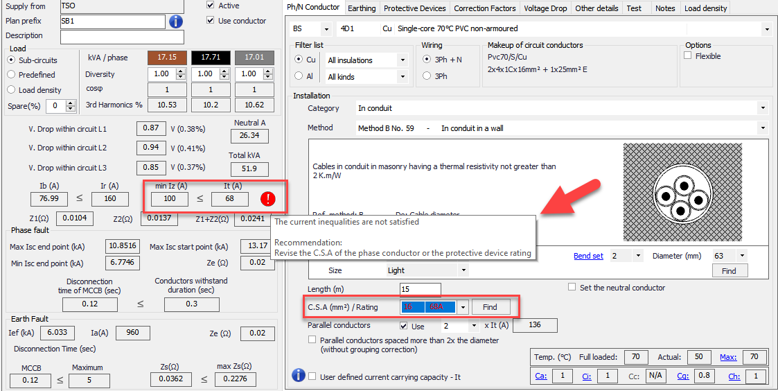
Calculations section is reserved for the calculations and checks done by ElectricalOM and none of the fields can be modified directly by the user. All the calculations and checks displayed in this area will automatically be recalculated and rechecked as the user makes any modifications to the system. If any issues detected, ElectrcialOM will flag this in the Warnings section and also mark the issue with a white exclamation mark inside a red circle.
As mentioned above, right hand side of the module screen is divided into various tabs and each tab screen is displayed below the tabs. Each tab will be discussed in its own section, please refer to these sections for details.
In general ElectricalOM will warn the user in various ways; and one of the ways is by white exclamation mark in red circles placed next to where the issue is. This is also true for Circuit Edit Module, the user can use these indicators to get a detailed explanation of the issue by moving the mouse cursor on to the marker.