Knowledgebase


Power Factor Correction Calculations
What is power factor?
Power quality is essential for efficient equipment operation, and power factor contributes to this.
Power factor is the measure of how efficiently incoming power is used in an electrical installation. It is the ratio of active to apparent power, when:
- Active Power (P) is the power needed for useful work such as turning a lathe, providing light or pumping water, expressed in Watt (W).
- Reactive Power (Q) is a measure of the stored energy reflected to the source which does not do any useful work, expressed in Volt Ampere Reactive (VAR). Reactive power does not perform useful “work,” but circulates between the generator and the load. It places a heavier drain on the power source, as well as on the power source’s distribution system.
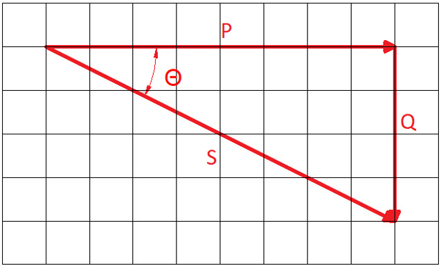
- Apparent Power (S) is the vector sum of active and reactive power, expressed in Volt Amperes (VA).
- Θ is the phase angle between voltage and current.
The power triangle:
Power factor is the ratio of active power to apparent power. It measures how effectively electrical power is being used. A high power factor signals efficient utilization of electrical power, while a low power factor indicates poor utilization of electrical power.
![]()
Higher currents increase the energy loss in a distribution system and require larger wires/cables and other equipment like protective devices. Because of the costs of larger equipment and wasted energy, electrical utilities will usually charge a higher cost to industrial or commercial customers where there is a low power factor.
As the triangle relationships above demonstrate, kVA decreases as power factor increases. For example, at 0.70 power factor, it requires 142 kVA to produce 100 kW.
![]()
However, at 0.95 power factor, it requires only 105 kVA to produce 100 kW.
![]()
Another way to look at it is that at 0.70 power factor, it takes around 35% more current to do the same work.
Power Factor Correction
Power factor correction (PFC) aims to improve power factor, and therefore power quality. It reduces the load on the electrical distribution system, increases energy efficiency and reduces electricity costs. It also decreases the likelihood of instability and failure of equipment.
Power factor correction is obtained via the connection of capacitors which produce reactive energy in opposition to the energy absorbed by loads such as motors, locally close to the load. This improves the power factor from the point where the reactive power source is connected, preventing the unnecessary circulation of current in the network.
Determining the required PFC using ElectricalOM
We will investigate a system with a load of 150KVA at pf of 0.8.
We set a predefined load at ADB: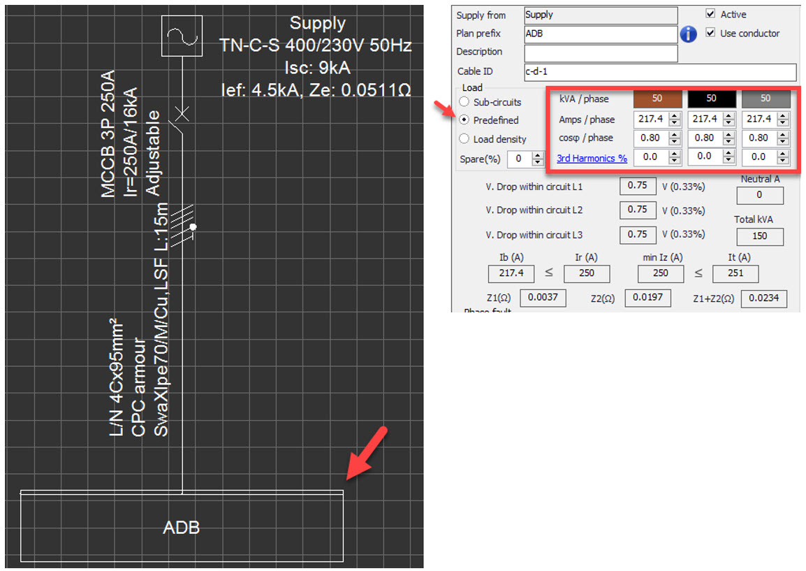
ElectricalOM will display a simple warning to indicate the pf is low and recommend power factor correction to be utilised.
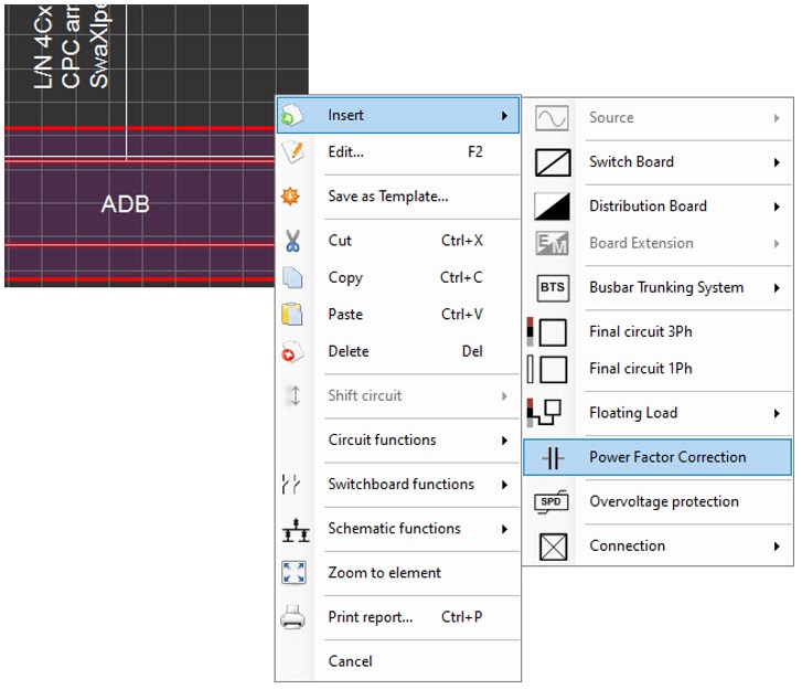
Now, we insert a PFC unit form the Insert menu:
By navigating to the Circuit edit tab of the PFC component, we can visualise reactive power and current associated with it when pf is set at different values using the Power factor correction field.
PFC component has a default power factor correction value of 1, which enables us to see the actual reactive power and current of the original circuit which is at pf of 0.8.
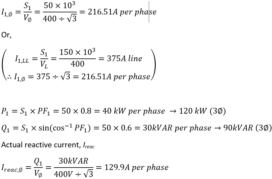
Actual active and reactive power, P1 and Q1

where;
I1,φ : initial phase current
Vφ : phase voltage
I1,LL : initial Line-to-line current
Ireac,φ : initial reactive phase current
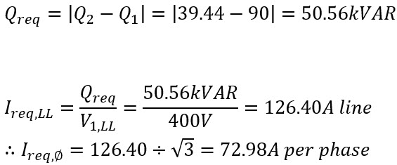
Required Reactive Power, Qreq
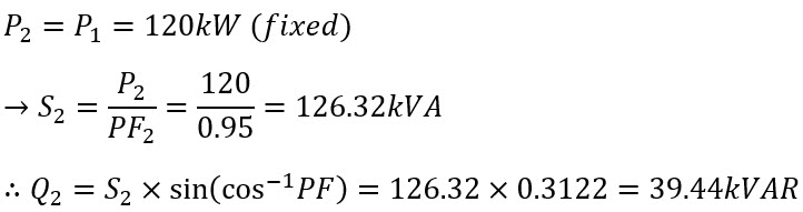
Let us say we want to increase our PF from 0.8 to 0.95. We set our Power factor correction to 0.95: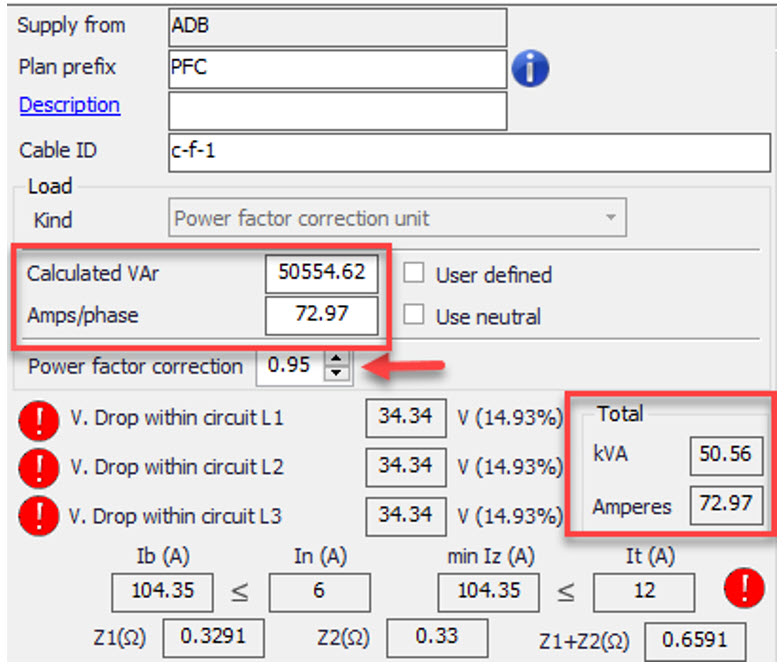
Required correction
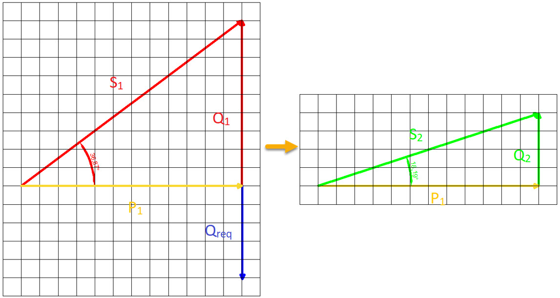
Below is a vector representation of the case we look at above. We reduced our reactive power from Q1 to Q2, and in order to achieve this, we introduced a reactive power of Qreq.
Calculating Design Current, Ib
Before calculating our design current, we will look into two IEC standards, IEC 60831 and IEC 60931, before we calculate our design current.
IEC 60831-1:2014
21 Maximum permissible current
Capacitor units shall be suitable for continuous operation at an r.m.s. line current of 1,3 times the current that occurs at rated sinusoidal voltage and rated frequency, excluding transients. Taking into account the capacitance tolerances of 1,1 CN, the maximum current can reach 1,43 IN.
These overcurrent factors are intended to take into account the combined effects of harmonics, overvoltages and capacitance tolerance according to 20.1.
34 Switching and protective devices and connections
The switching and protective devices and the connections shall be designed to carry continuously a current of 1,3 times the current that would be obtained with a sinusoidal voltage of an r.m.s. value equal to the rated voltage at the rated frequency. As the capacitor may have a capacitance equal to 1,1 times the value corresponding to its rated output (see 7.2), this current may have a maximum value of 1,3 × 1,1 times the rated current.
IEC 60931-1:1996
21 Maximum permissible current
Capacitor units shall be suitable for continuous operation at an r.m.s. line current of 1,3 times the current that occurs at rated sinusoidal voltage and rated frequency, excluding transients. Taking into account the capacitance tolerances of 1,15 CN, the maximum current can reach 1,5 IN.
These overcurrent factors are intended to take into account the combined effects of harmonics, overvoltages and capacitance tolerance according to 20.1.
34 Switching and protective devices and connections
The switching and protective devices and the connections shall be designed to carry continuously a current of 1,3 times the current that would be obtained with a sinusoidal voltage of an r.m.s. value equal to the rated voltage at the rated frequency. As the capacitor may have a capacitance equal to 1,15 times the value corresponding to its rated output (see 7.2), this current may have a maximum value of 1,3 x 1,15 times the rated current.
ElectricalOM considers the newer standard, IEC 60831:2014, to calculate the design current, Ib:
![]()
Capacitor Bank Restrictions
However, due to capacitor ratings, we may not be able design a capacitor bank with an exact reactive power value of 50.56 kVAR. As an example, let us say we managed to set up a 55 kVAR PFC system instead of 50.56 kVAR.
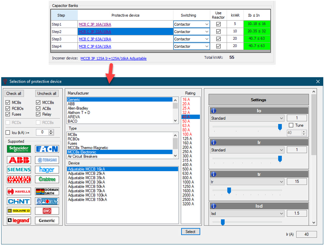
We add our PFC system using the Cosφ Correction tab of the PFC component. First, we tick the Power Factor Correction Panel box, then, we add our capacitors one by one using the Add Capacitor Bank button. We set the capacitor ratings by clicking inside the kVAR field and typing in the desired value.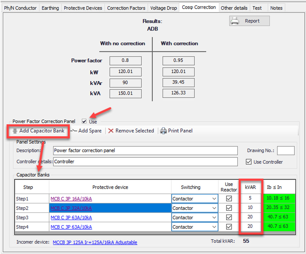
As we set ratings, ElectricalOM will warn us about the rating of the protective device by highlighting the Ib ≤ In cell either in red or green. We can set a protective device by clicking on the link for that protective device.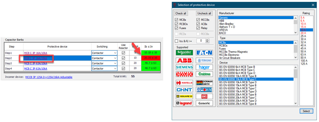
Cosφ Correction tab will display the parameters of the system with and without PFC on the top of the screen. It should be noted that “with correction” values are for the set pf (on circuit edit tab of PFC component), and not the pf after the capacitor bank.
At the bottom, total kVAR of our capacitor bank is displayed, which is 55kVAR at the moment. The protective device can also be selected to suit to this value. ElectricalOM will display a red exclamation mark symbol if the selected protective device is not suitable. There will not be a warning in Warnings area.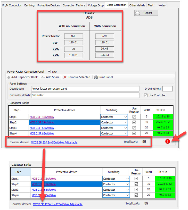
Recalculating design value after PFC system, Ib,PFC
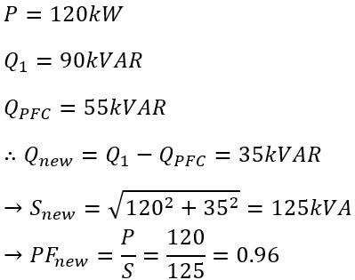
Now, we will recalculate our design current for a 55kVAR PFC system:
where;
Q1 : initial reactive power
QPFC : reactvie power of PFC
Qnew : reactvie power after PFC
Snew : power after PFC
PFnew : power factor after PFC
Again, the vector representation of Qnew after installation of the PFC system (QPFC) is shown below:
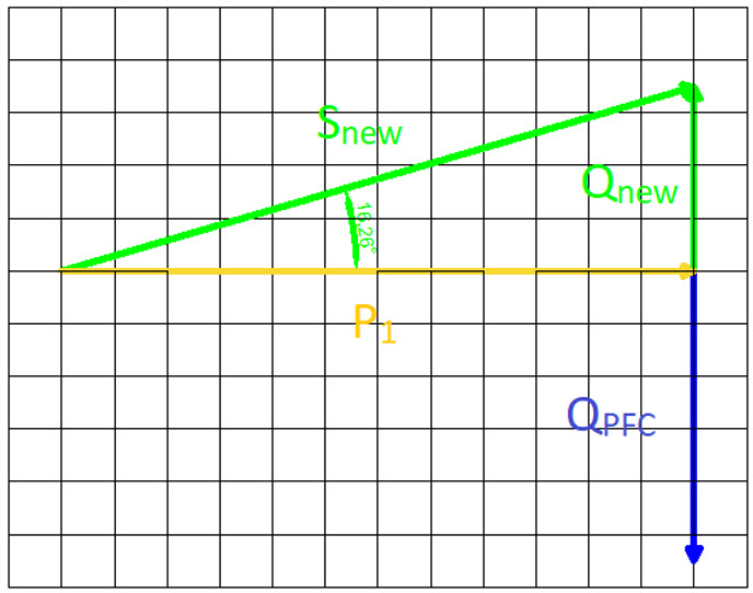
So, our design current for 55kVAR will be:
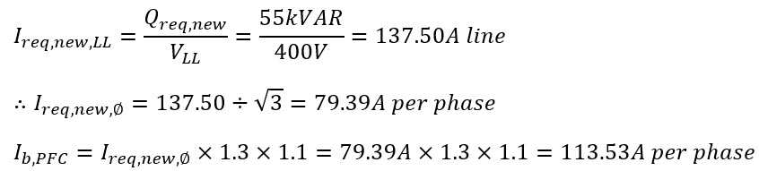
where;
Ireq,new,LL : required line-to-line current
Ireq,new,φ : required phase current
Ib,PFC : design current after PFC
That is why ElectricalOM will highlight protective device ratings below 113.53A with red for the PFC system. See below:
Summary
Now, just to visualise what we achieved by using a PFC, and rising the PF from 0.8 to 0.96:
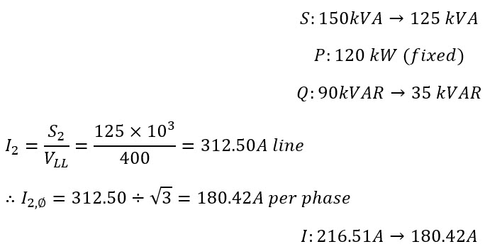
So, at the end, we managed to reduce our current draw around 36A per phase for the same amount of P, 120 kW.
Also Read
-
Arc Fault Detection Devices - AFDD (Views: 7245)
-
Exploring PD CLC/TR 50480:2011 and the UK National Annex NA: Additional Earth Conductors and Steel Armour in Parallel (Views: 1797)
-
Max Zs Calculation (Views: 52964)
-
Cables Buried and/or Ducted Current Carrying Capacities - The rating differences between BS7671 and the ERA in ElectricalOM (Views: 20055)
-
Selectivity Study (Views: 15535)
About Us
Modecsoft ElectricalOM is a Powerful, Fast & Accurate Software for Low Voltage Electrical Design, Modeling and Certification. Calculations and Checks Compliance with BS 7671:2018 and IEC 60364


Testimonials

Copyright © 2026 MODECSOFT Ltd. All Rights Reserved.
Privacy Policy Terms and Conditions Purchase and Refund Policy Software License Technical Support Policy