Announcements
ElectricalOM Update 2017.11.08.01
Wednesday, November 8, 2017
We have updated ElectricalOM to version 2017.11.08.01. In this version, along with the new features, we have made lots of improvements to performance and to the existing functionalities.
Some of the features of the new version are listed below:
1. Plan Design Additions
1.1 Walk-through Functionality with 3D Representation of Spaces and Columns
In Plan Design 3D View, the user can now use the walk-through functionality to easily navigate through the 3D model. Also spaces and columns are represented in 3D, providing a more realistic view of the 3D placement of the electrical installation’s components.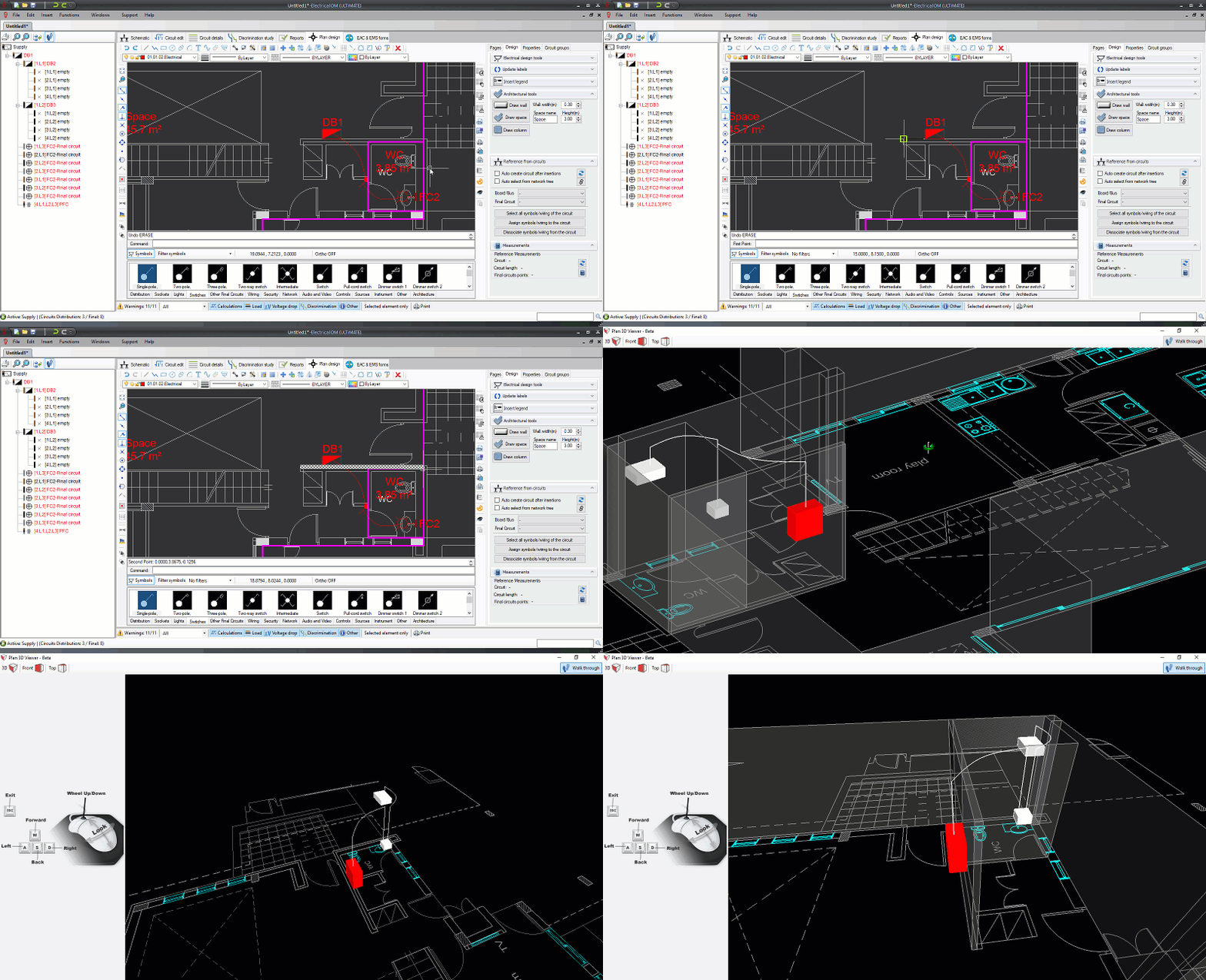
1.2 Electrical Takeoff and Estimation Features: Materials codes for symbols/wires
The user can associate with every symbol and wire section user defined item codes to describe materials associated with that particular item. Special length associated codes such as cable runs, conduits, etc. can be assigned also to a wire section. 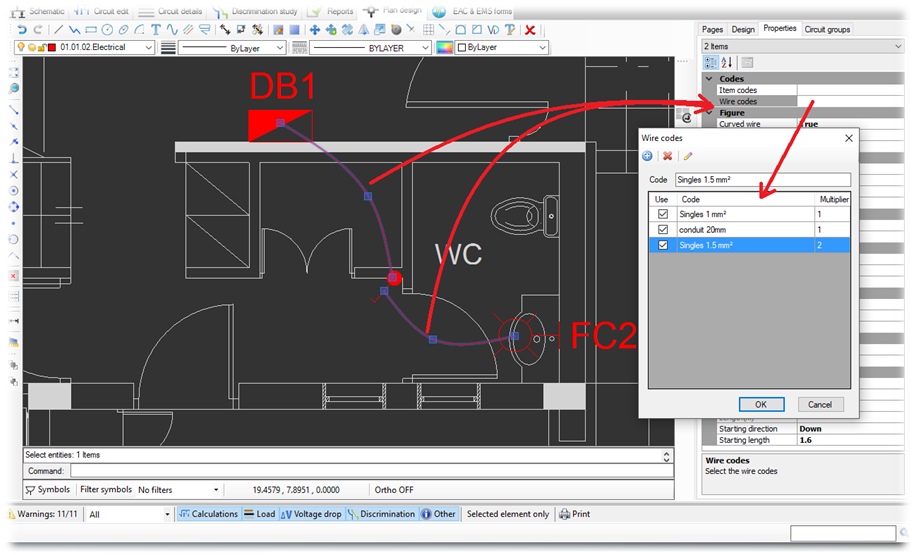
1.3 List of Materials Report
The sums of the item and wire codes associated with the electrical symbols/wire sections appear in the List of Materials Report. This report can be used for takeoffs and estimations. 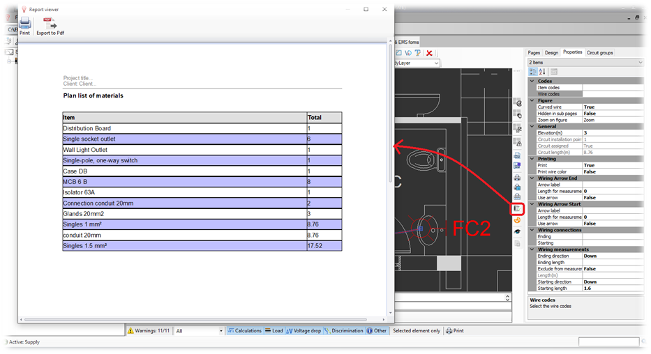
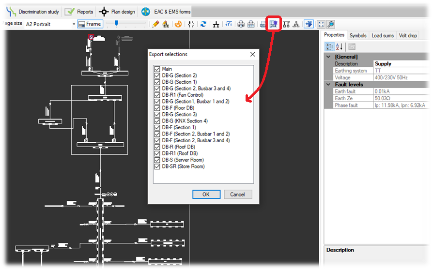
1.4 Multipage Export
The multipage export functionality allows the export of the selected pages with a single click.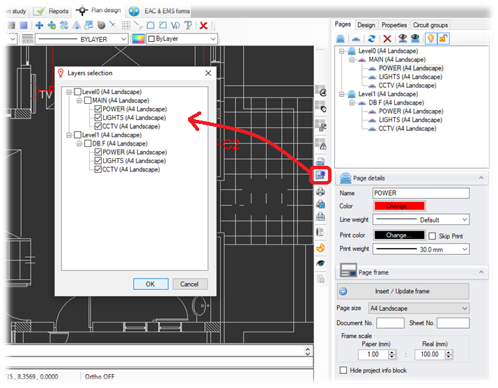
1.5 Improved Wiring Connections
The improved functionality allows the user to check the symbols that are connected by a wire section and thus make sure that the elevations and extra lengths have been correctly set. This can be done from the properties area of the selected wire section. The connected symbols can be then expanded and modified if required.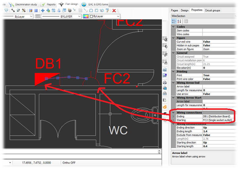
2. Compacted Mode for Distribution Circuits
The compacted mode hides all the final circuits connected to the distribution circuit. This functionality is useful in large projects where the engineer needs to focus on the distribution network structure in a single page. If required, the designer can choose to display one or more circuits to illustrate for example important loads or equipment.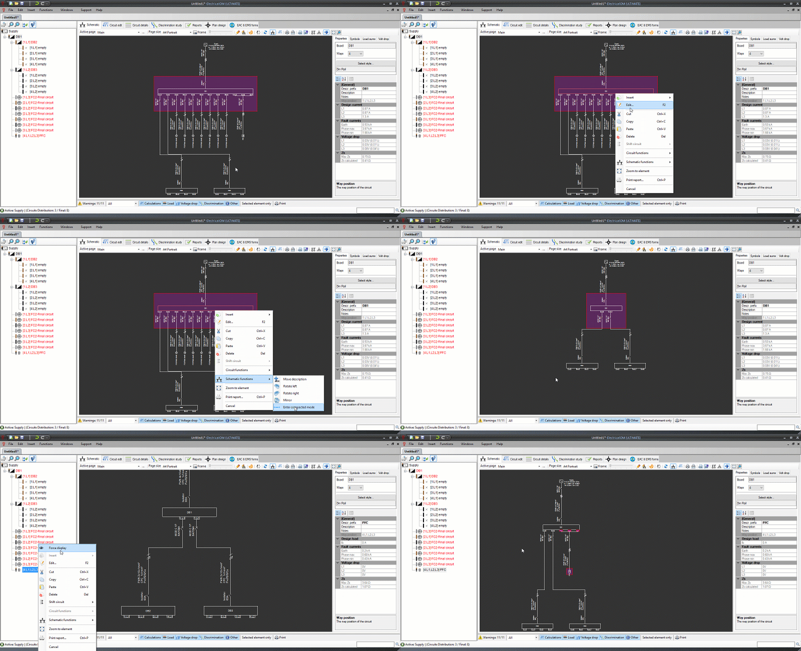
3. Switches Configurations
Persisted switches configurations enable the engineer to easily activate part of the electrical distribution based on the saved switches state. This is very useful in projects with multiple sources and complex switching arrangements where the designer needs to calculate and verify the installation for many switching scenarios.
Click the image below to see a video that demonstrates this functionality: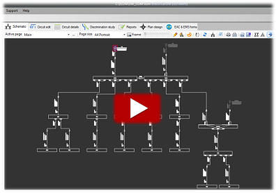
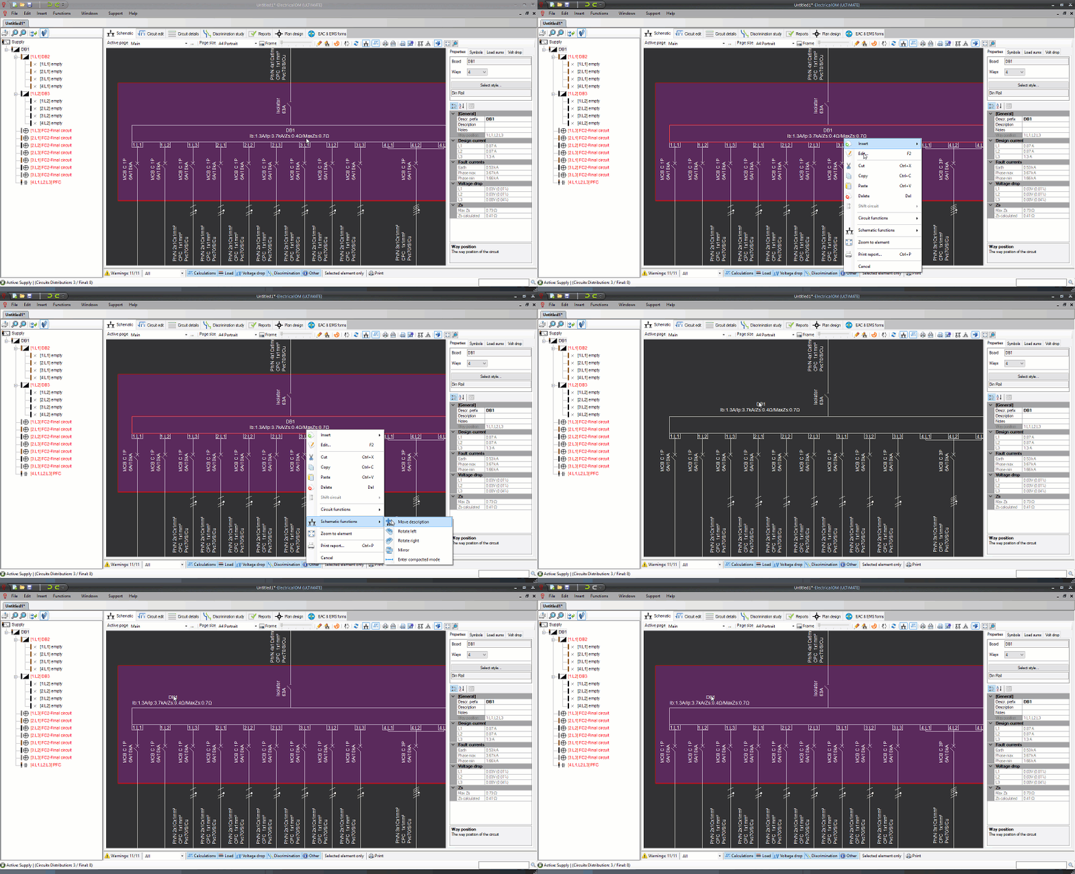
4. Move Labels
Labels in the schematic diagram can now be moved and placed in any location according to user needs. See an example below:
5. Symbol Text Edit and Size
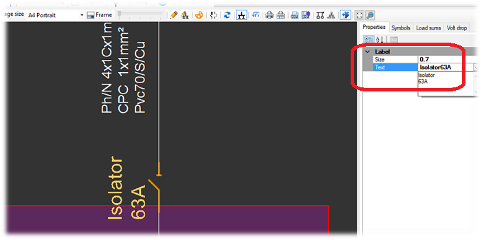
In this version the user is able to modify the selected symbol's text and size from the properties area as shown below:
6. Labels Size Functionality for Multiple changes in the Schematic
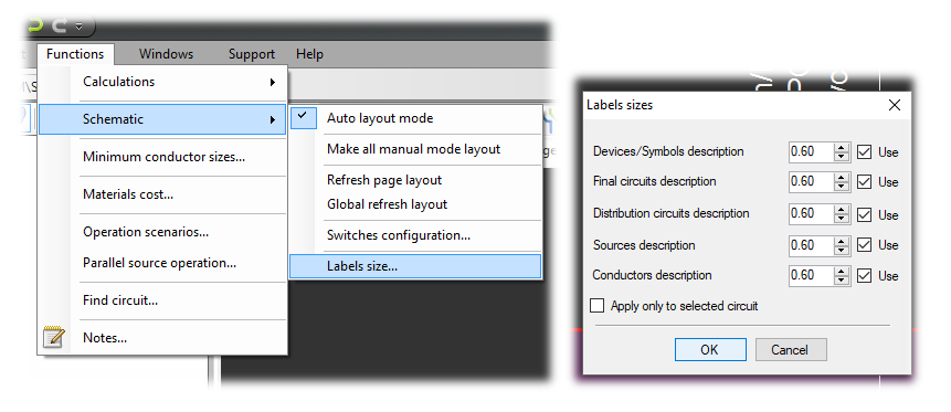
The labels size functionality (Main menu Functions -> Schematic -> Labels size...) enables the user to make multiple changes with a single click to the labels size in the active page.
7. Schematic Multi-Page Export
With this functionality, the user is now able to export all or a number of selected pages at once.
