Knowledgebase
ElectricalOM Update 2020.04
What's new?
1. New functionality
1.1 Multi selections in schematic
With the multi selections, you will be able to quickly rearrange the network and perform actions to multiple items
1.2 Colouring groups
Use the colouring groups to annotate circuits based on colours. Also, the colouring group can be listed in the schematic cable schedules.
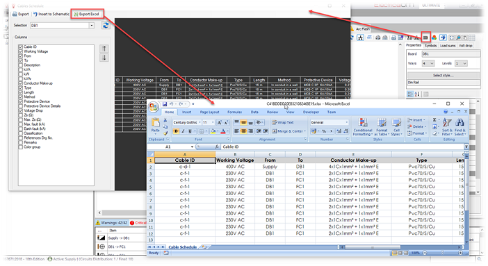
1.3 Export schematic cable schedules to Excel
You can now export the schematic cable schedules directly to excel by clicking on the new excel export button
1.4 Project Lock
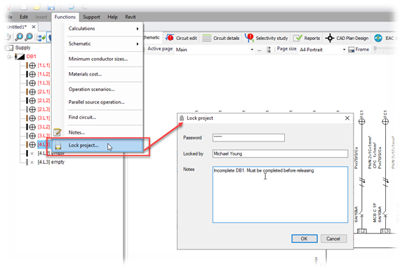
The Project Lock function enables the user to password-protect their projects from being accessed by other users. During the locking functionality, the user must enter the password key, and may input the name responsible for the lock and a note to explain the reason for locking the project.
The project can be unlocked by entering the password key, during the opening.
1.5 RCBO RCD class type selection
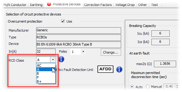
The Engineer can now specify the RCD class type of the RCBO device. This selection will appear in the schematics and also listed in the schedules.
1.6 High Voltage settings
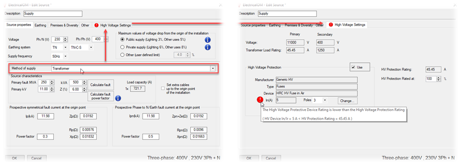
The High Voltage (HV) setting appears when a Transformer is defined as the method of supply. The settings are related to the HV device used on the primary side of the Transformer and checks are performed based on the Transformer's rating and the rating of the HV device selected. Also, when a HV device is defined, ElectricalOM will perform Selectivity checks between the HV and LV devices.
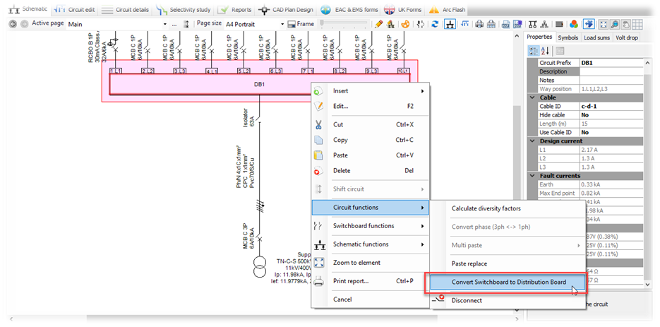
1.7 Convert Switchboard to Distribution board and vice versa
This functionality will enable the Engineer to quickly convert a Switchboard to Distribution Board and vice versa. Please note that during this function any multiple sources defined in the switchboard will not be preserved.
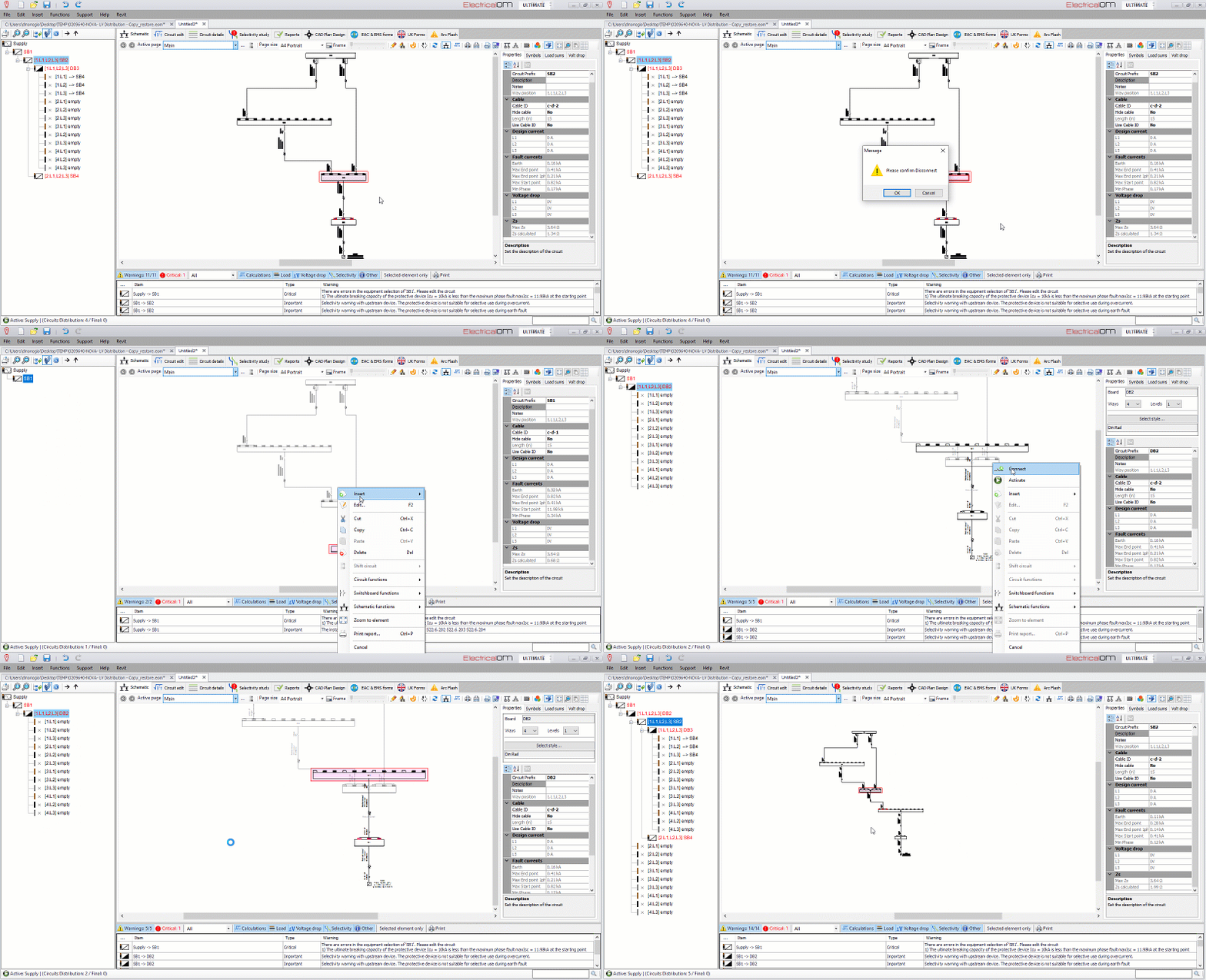
1.8 Disconnect/Reconnect functionality
The disconnect functionality removes a distribution circuit from the active network, in order to reconnect it to a new position. Also with this functionality, the Engineer will be able to rearrange the upstream network, without losing any paging and/or multi-sources defined.
A typical example can be the insertion of a new distribution circuit in-between two existing ones. To be able to do this in older versions of ElectricalOM you had to use cut and pasting which did not preserve paging and/or multi-sources defined. Now with the new disconnect/reconnect functionality this can be achieved without the need to re-create pages and/or multi-sources.
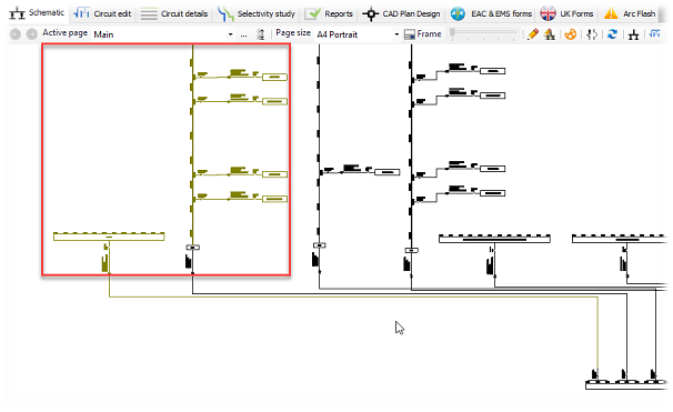
1.9 Colouring of the inactive circuit.
Now any inactive circuits will be identified easily from the olive colour in the schematic.
1.10 Extra cable options
The Engineer can choose to describe cables as LSZH (Low Smoke Zero Halogen) and/or as FP (Fire Proof) from the circuit editor's cable options. These options will be applied in the cable make-up description which is displayed in schematic diagrams and cable schedules. These options are also available in the Circuit details tab, for quick multiple changes.

1.11 Improvements in the Circuit Editor
- Display of cable Full load and Actual temperatures, in the cable selection tab
- Display of the cable sizing correction factors currently applied, in the cable selection tab

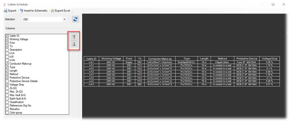
1.12 Improvements in schematic cable schedules
Ability to move columns in schematic circuit schedules and new columns included.
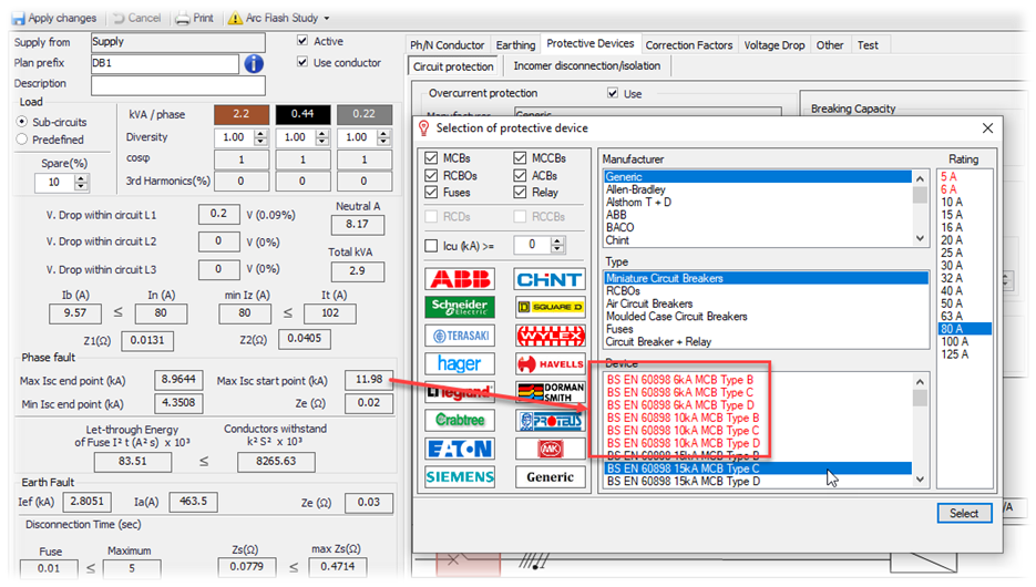
1.13 Highlight with Red, devices failing the breaking capacity limit
During the device selection, any device not able to withstand the maximum fault level at the starting point of the circuit will be marked with red colour. This makes the selection process easier and faster.
1.14 Spare and spaces analysis in the circuit schedules report
The circuits schedule report will now list spares and spaces information below the top frame

1.15 Other improvements
- Indicate the 0.4 and 5 sec line in the Selectivity study curves
- Improvements in circuit details tab: quick selections, maintain selections across tabs
- Extension board numbering in schematic
- Default Properties in Project info and options: Run to 70, LSF (if applicable), Enable Current Limiting Effect
2. Calculations and Checks
2.1 Consideration of reg. BS7671:2018 433.2.2, that allows a maximum distance of three metres between the overload device
2.2 Combined neutral calculations in AC/DC Converters
This setting will affect the calculated neutral current of the converter connection, as per the total number of rectifiers defined.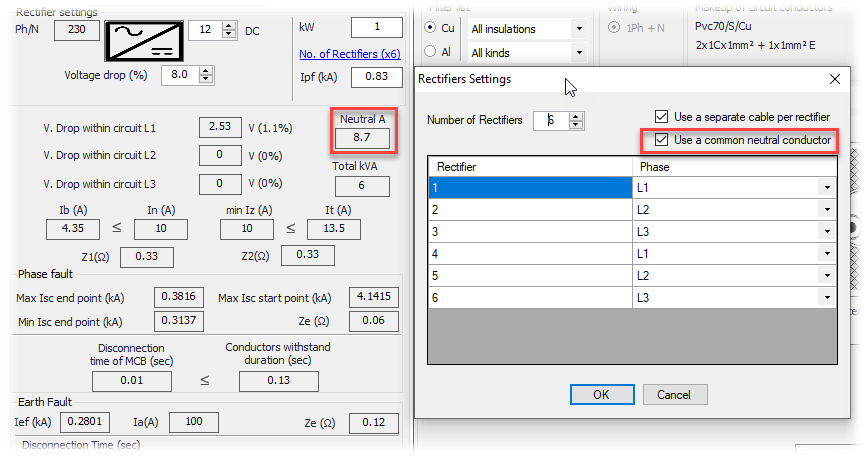
2.3 Table 54.7 check for the main earthing conductor
This option will force the main earthing conductor's size check to be performed in accordance with Table 54.7 of B7671, instead of the default adiabatic equation check. 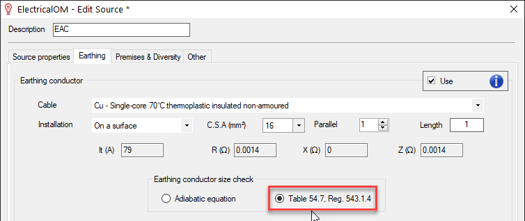
2.4 High voltage device checks and selectivity checks between HV and LV devices
If the Engineer chooses to define HV equipment, this will be verified against the rating of the transformer. Also, the software will perform selectivity checks between the HV and the downstream LV device
2.5 Generator fault levels as per CENELEC CLC/TR 50480
When defining a generator, the settings will be initialised based on the CENELEC CLC/TR 50480 technical publication.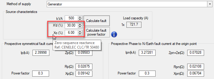
2.6 Transformer Impedance percentage levels
Transformer Impedance percentage levels are now updated as per IEC 60076-5:2000
2.7 Criteria for type gG fuses - Comply with the IEC Standard requirement
As per the IEC standard, the condition I2 ≤ 1.45 Iz must be taken into account, where I2 is the fusing (melting level) current, equal to k2 x In (k2 ranges from 1.6 to 1.9) depending on the particular fuse concerned. In such a case an extra factor k3 = 1.31 for fuses with In < 16A, or k3 = 1.1 for fuses with In ≥ 16A is considered, in order that I2 ≤ 1.45 Iz will be valid if In ≤ Iz/k3.
This check can be selected at the "Checks" tab in the project info and options dialog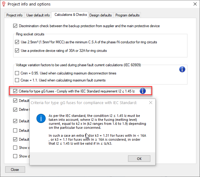
3. New reports
3.1 Motor starting analysis
The motor starting analysis report will list all motor circuits and their settings which are related to the motor starting and contribution to the fault levels. Also, the report will list the voltage drop behaviour during starting

3.2 Selectivity results
The selectivity results report will list all selectivity checks performed and the outcome of each check

4. CAD Plan design Add-on updates
4.1 Cable schedules to cad plan
Watch the video to see how to insert cable schedules in your CAD Plan design drawings
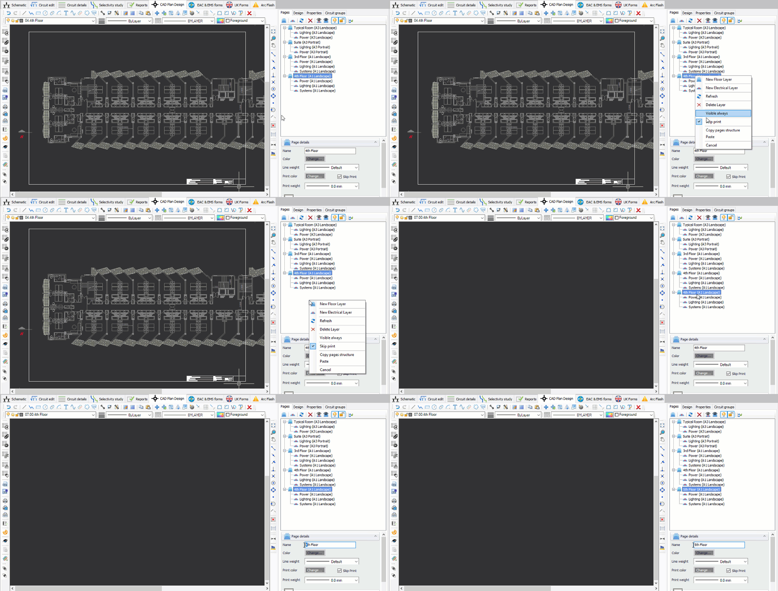
4.2 Copy pages structure
The Engineer can now quickly replicate an existing structure of the pages
4.3 Pages rearrangement
The Engineer can now move pages up or down allowing the ordering and rearrangement of the structure of the pages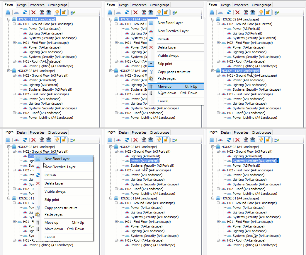
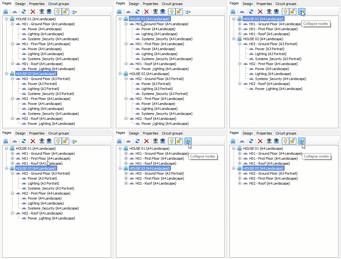
4.4 Collapse all pages
This function will enable the collapse of all pages of the selected page group
4.5 Multicolour symbol
A new "Monochrome" symbol property has been introduced to allow multicolour symbols. The monochrome option is also available in the symbol editor in order to define the symbol's default behavior 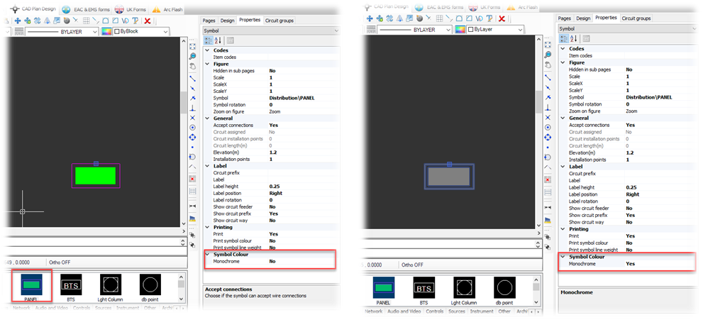
5. New cables
The new cables added in the new version are listed below:
- SY Steel Wire Braid Flexible PVC Control Cable BS EN 50525-2-11:2011
- TFL-NKT DC Cable (up to 35mm2)
- Energy, signalling or controls with copper braid shield LSZH EN 60228 Class 5
- Prysmian FP PLUS Fire Resistant
- BS 7870 Split Concentric Cable
6. New protective devices
The new protective devices added in the new version are listed below:
- Schneider: MTZ Range, Easy Pact EZC100H, EZC100N
- General Electric: MCCBs and ACBs devices
- Siemens: 3VT MCCBs
- EATON Memshield 2 MCCBs
- Eti Group devices
- LSIS devices
- Allen-Bradley devices
- Ferraz Shawmut, BS88 Current Limiting Fuses
- Generic IEC EN 60269-1 Fuse
- Generic High Voltage Fuses
- Generic High Voltage Relays
- CBi electric DC breakers
- Nader DC breakers
- BACO Circuit Breakers
7. New busbar trunking systems
The new busbar trunking systems added in the new version are listed below:
- EAE ELEKTRIK - E-Line
- Legrand - Zucchini 2018
- EATON - Power Xpert
- Siemens - Sivacon
- E&I Engineering - Powerbar
Also Read
-
ElectricalOM Update 2017.11.08.01 (Views: 2886)
-
ElectricalOM Initial Release (Views: 3252)
-
ElectricalOM Update 2018.06.12.01 (Views: 3949)
-
ElectricalOM Update 2018.08.14.01 (Views: 4220)
-
ElectricalOM Update 2017.06.27.02 (Views: 2265)


