Knowledgebase
ElectricalOM Update 2018.06.12.01
Some of the features of the new version are listed below:
1. Improved Busbar Trunking System Modeling. Watch the video here: https://www.youtube.com/watch?v=wiFzNwBzkNQ&feature=youtu.be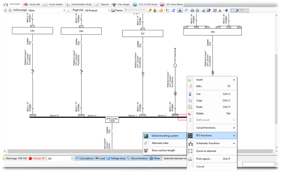
2. User defined conductor current carrying capacity (It)
This option will enable the user to overwrite the phase conductor current carrying capacity (It). Please use this option with caution and only when specific cable ratings are provided by manufactures' data. Also a simple warning will be displayed to indicate this selection.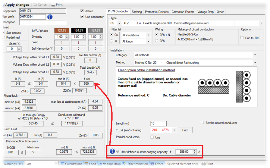
3. Fuses parallel assembly
In this version we have implemented the fuses parallel assembly, allowing the user to model extreme cases where more than one fuse links have to be installed in parallel. In theory, the rated current (In) of the assembly is the rated current of the component links multiplied by the number of the fuses in parallel. In practice, taking account of the proximity of the links and imperfections in current distribution, the rated current of the assembly is de-rated.
In particular for the parallel assembly modeling of N fuses we are considering the following calculations:
This setting can be defined during the protective device selection. It is highly recommended to get advice from the manufacturer's specifications when applying this setting.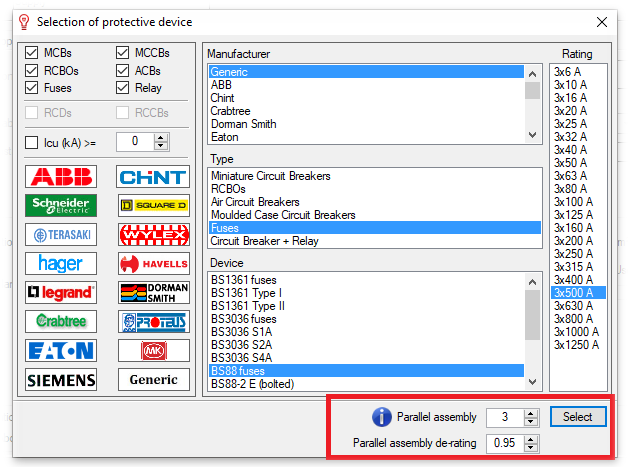
4. Centre Tap Earth (CTE) Transformer
In the new version we included the option for setting a transformer connection as Centre Tap Earth (CTE). CTE systems are commonly used for site safety portable tools. The centre tap splits the winding into 2 sides, each having only the half of the secondary voltage with respect to earth.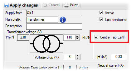
5. RCD as additional protection only
In TN earthing systems it is considered as good proctice to perform validations of the maximum earth fault loop impedances based on the overcurrent protective device and not "rely" on the RCD operation, which in this case is considered as a additional protection equipment only. This option is now available and can be selected by checking the "RCD devices are used only for additional protection" option in the circuit editor at the circuit protective devices tab page.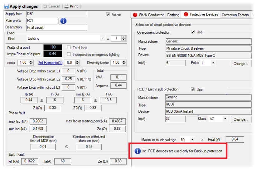
6. Multi-core CPC cores selection
The user can now define the number of cores that will be used as the circuit protective conductor (CPC) in a multi-core cable.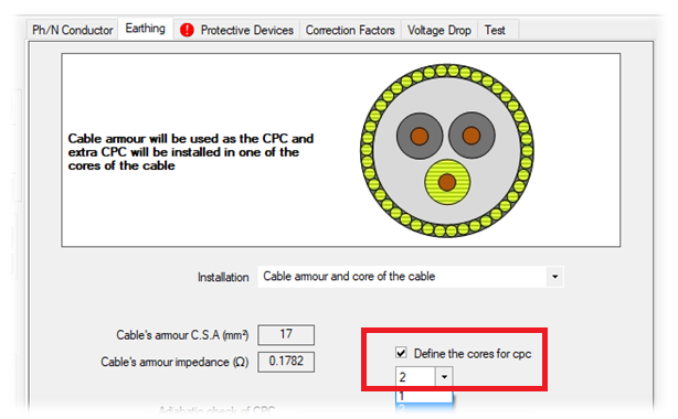
7. Emergency lighting option for lighting circuits
Lighting circuits can now be selected to include a check for emergency lights. This will include an extra core in the cable, to accommodate the emergency lighting requirements.
8. New circuit types added
In the new version we included new circuit types in the load kind list:
- Industrial Sockets (EN 60309-2)
- Air Source Heat Pump
9. Grid on schematic
The Grid option (1) can be enabled to help with moving the schematic elements based on a grid distance margin (3), defined in the palletes option (2). The color of the grid line can be defined in the palette options at the colors tab page.

10. New reports
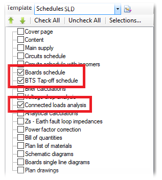
In the new version we included 3 new reports:
- Boards schedule: Lists all boards used in the active network design
- BTS Tap-off schedule: Lists all Busbar trunking systems with tunking sections details and tap-off arrangment
- Connected load analysis: Produces an analysis of the load kinds used in the installation and in each distribution circuit
11. Report selection templates
This functionality allows the user to create templates of the reports selections. This will enable fast and easy selections of the desired reports to be included in the generated print out.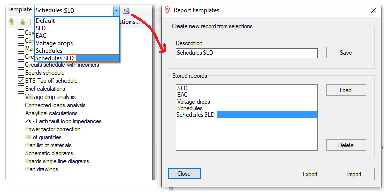
12. CAD Plan design additions
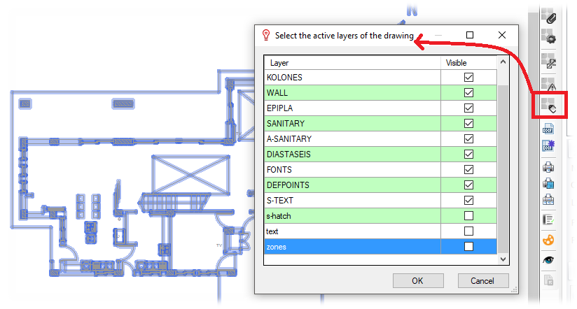
Xref layers visibility
The user can now choose the show/hide the layers of the selected Xref drawing.
13. New Protective Devices Added
In the new version we included new protective devices from several manufacturers.

14. New Cables Added
Two new cables types have been added to the cables library: The Coil End Lead Class 5 flexible tinned copper conductor according to BS EN 60228 (previously BS 6360) and the Prysmian FP600S Fire Protection Cable.
Also Read
-
ElectricalOM Update 2020.10 (Views: 5460)
-
ElectricalOM Update 2020.04 (Views: 19457)
-
ElectricalOM Update 2021.06 (Views: 5183)
-
ElectricalOM Update 2017.04.06.02 (Views: 8656)
-
ElectricalOM Update 2017.08.24.01 (Views: 2813)


