Knowledgebase


Using Switchboard Coupling in ElectricalOM
Switchboard coupling in ElectricalOM allows you to interconnect panels, simulate redundancy, and carry out realistic load flow and protection studies. This guide explains how to insert a coupling between two switchboards, close it to select a supply, and configure protective devices and cabling.
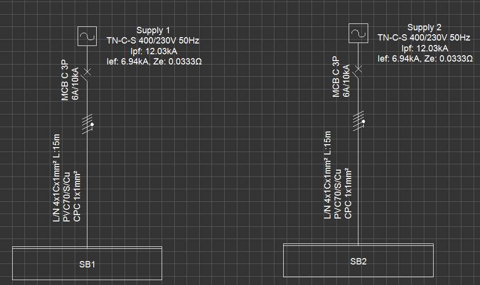
We start with a project where:
- Supply 1 → SB1
- Supply 2 → SB2
are already defined and placed on the screen.

Step 1 – Insert a Coupling Between SB1 and SB2
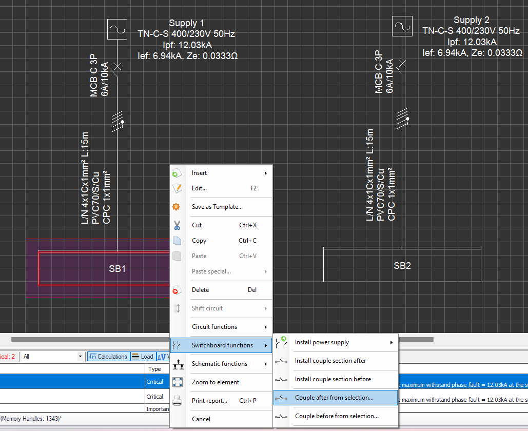
- Right-click on one of the switchboards (e.g., SB1 or SB2).
- From the context menu, go to Switchboard Functions.
- Select one of the following:
- Couple before the selection – inserts a coupling on the left-hand side of the selected switchboard.
- Couple after the selection – inserts a coupling on the right-hand side of the selected switchboard.
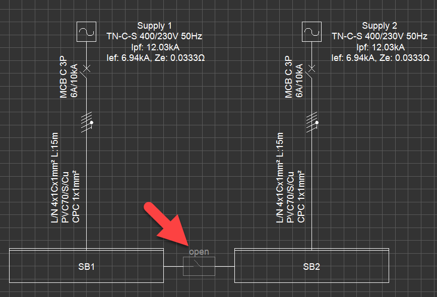
⚡ Notes:
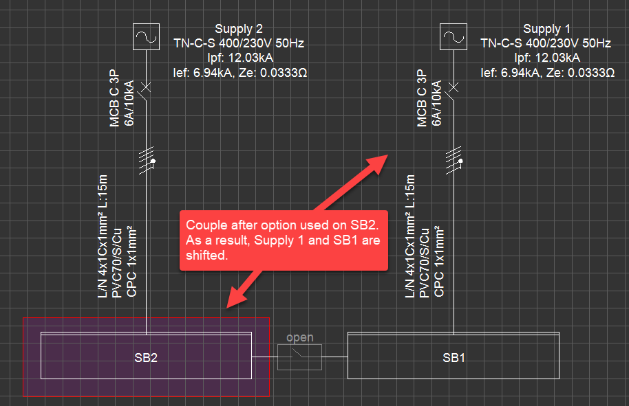
- Depending on which option you select, the other supply and switchboard may shift position.
- The new coupling appears in the open state (inactive).
- No protective devices or cabling are assigned at this stage.
Step 2 – Close the Coupling and Select the Active Supply
- Double-click the coupling to close the coupler.
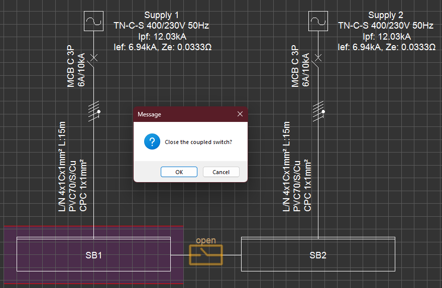
2. Select OK to change the state to Closed.
3. ElectricalOM will ask via which switchboard the system should be supplied (e.g., SB1 or SB2).
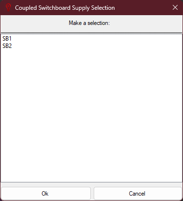
4. Once confirmed:
- The chosen supply remains active.
- The other supply is deactivated.
- The non-supplying switchboard is now fed via the coupling.
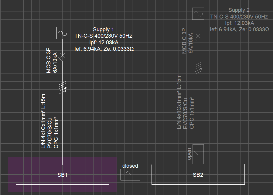

Example:
If SB1 is selected as the supply path:
- Supply 1 → SB1 → Coupler → SB2 becomes the active chain.
- Supply 2 is disabled.
Step 3 – Add Protective Devices
On the Supplying Switchboard (SB1)
The supplying switchboard (SB1) continues to operate as usual. Any protective devices or cabling set here remain between the active supply (Supply 1) and SB1 — nothing changes for the supplying panel.
On the Supplied Switchboard (SB2)
Once the coupling is closed and SB2 is supplied through SB1, the logic of the protective device settings changes. SB2 no longer has its own active source; instead, it receives power via the coupler.
In this case:
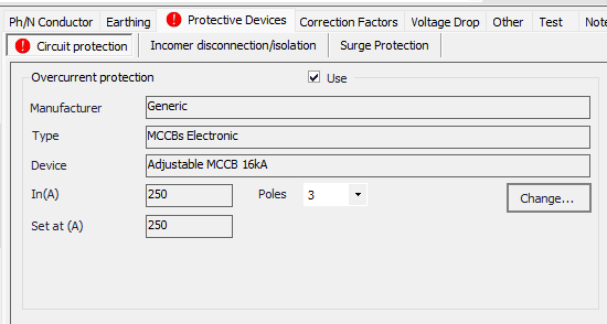
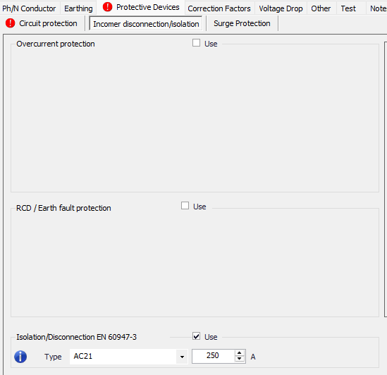
- Circuit Protection tab
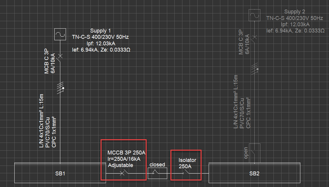
Defines the protective device placed upstream of the coupling, downstream of SB1. This represents the overcurrent protection for the line feeding SB2 through the coupling. - Incomer Disconnection/Isolation tab
Defines the protective device placed downstream of the coupling, upstream of SB2. This represents the disconnector or isolator at the entry point of SB2.
- Double-click SB2.
- Open Circuit Edit → Protective Devices.
- Configure devices depending on location:
- Circuit Protection tab – sets devices upstream of the coupling (downstream of SB1).
- Incomer Disconnection/Isolation tab – sets devices downstream of the coupling (upstream of SB2).
⚡ Important:
- SB2 now “sees” SB1 as its supply.
- Any OCPDs set here represent the devices between SB1 and SB2 across the coupler.
Step 4 – Add Cabling (Optional)
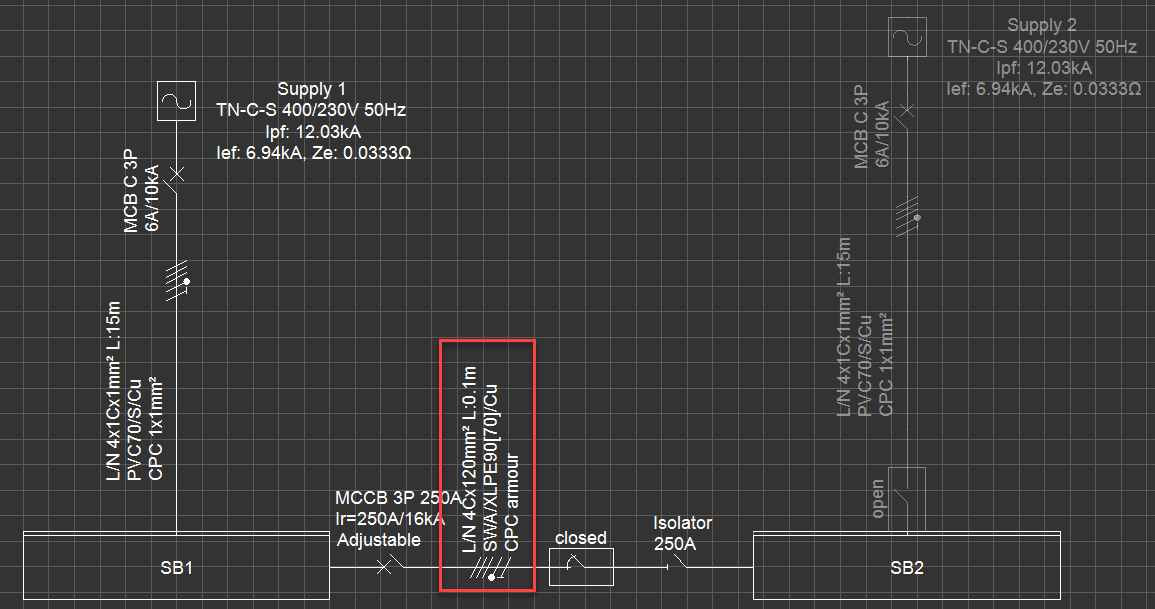
- If this option is selected, ElectricalOM automatically inserts a cable between the supplying panel (SB1) and the coupler. This cable represents the physical connection that carries power from SB1 to SB2 through the coupling.
- Tick Use Conductor Box in the SB2 settings.
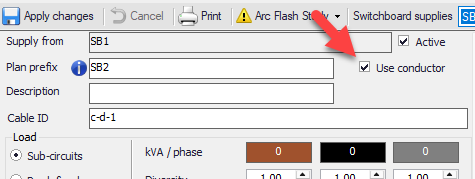
3. ElectricalOM will automatically insert cabling between the supplying switchboard and the coupler.
- If SB1 is the active source → cable is drawn from SB1 to the coupler.
- The length of the cable will be set to 0.1m by default.
Also Read
-
ElectricalOM User Manual (Views: 3730)
-
Feeding Three Single-Phase Rectifiers from a Three-Phase Board (Views: 486)
-
Multiple circuit selection and QA tools (Views: 1715)
-
UPS Maintenance By-pass Modelling (Views: 836)
-
Ring distribution systems (Views: 791)
About Us
Modecsoft ElectricalOM is a Powerful, Fast & Accurate Software for Low Voltage Electrical Design, Modeling and Certification. Calculations and Checks Compliance with BS 7671:2018 and IEC 60364


Testimonials

Copyright © 2026 MODECSOFT Ltd. All Rights Reserved.
Privacy Policy Terms and Conditions Purchase and Refund Policy Software License Technical Support Policy