Knowledgebase
Max Zs Calculation
For TN earthing systems, the Max Zs formula derives from regulation 411.4.4: Zs x Ia ≤ Uo x Cmin => max Zs = Uo x Cmin / Ia
Where:
Zs: Earth fault loop impedance
Ia: The current in amperes (A) causing the automatic operation of the disconnecting device within the time specified in Regulation 411.3.2.2
Uo: The Nominal AC rms or ripple-free DC line voltage to Earth
Cmin: The minimum voltage factor to take account of voltage variations depending on time and place, changing of transformer taps, and other considerations. Cmin is given the value 0.95.
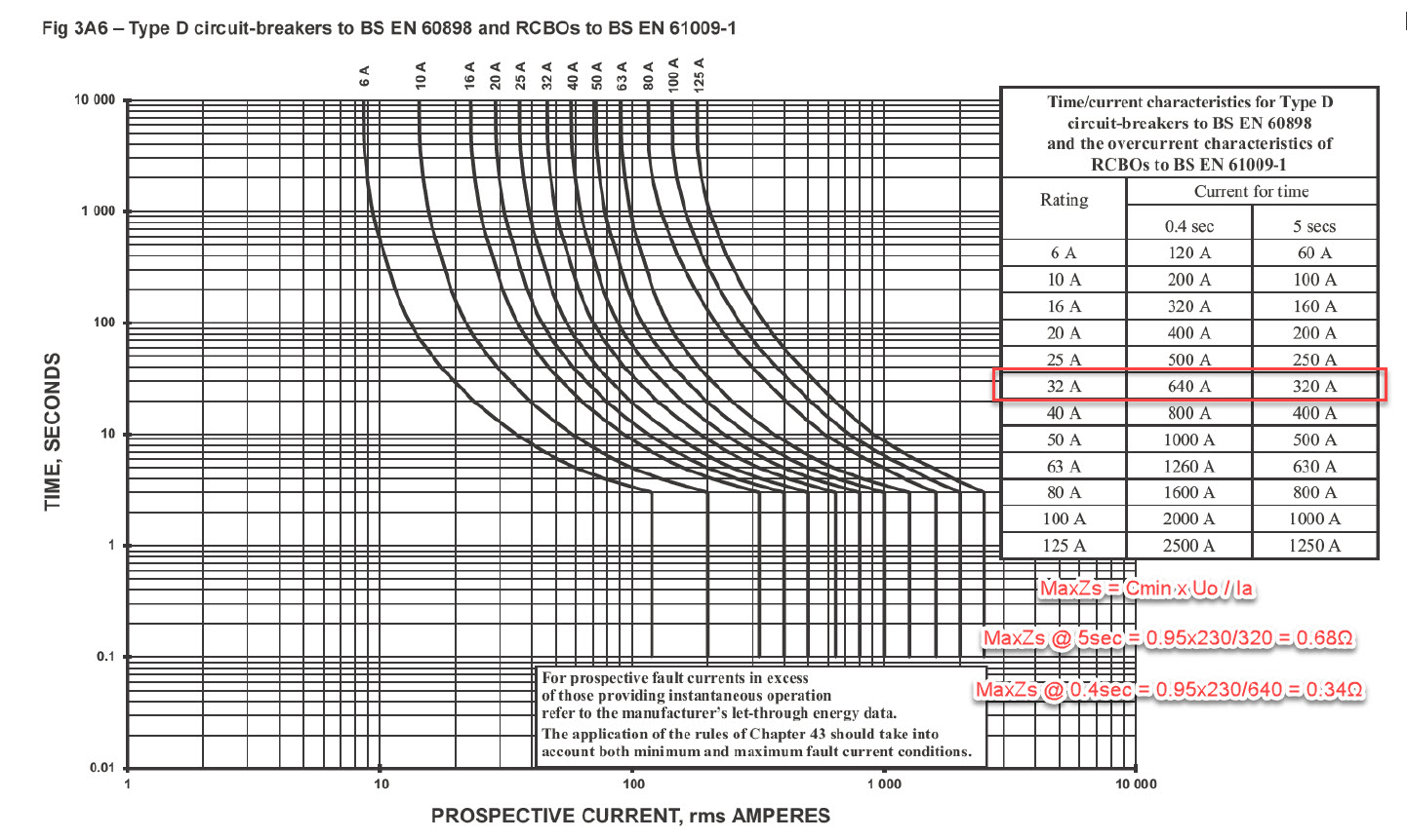
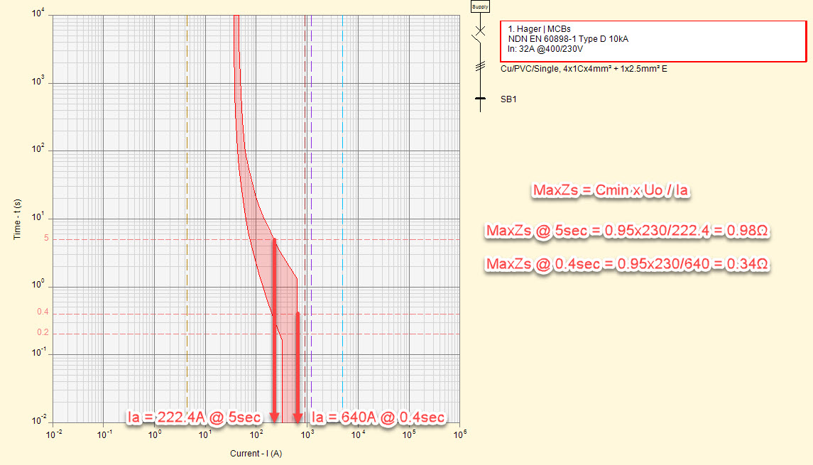
Based on the above formula, in order to calculate the max Zs we need to find the Ia for the specified time constraint (i.e. 5sec, 0.4sec, etc.). This is done using the Time-Current curve of the protective device.
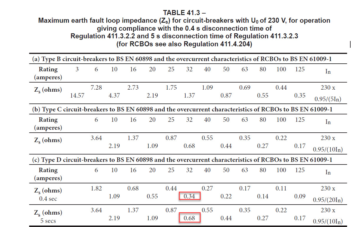
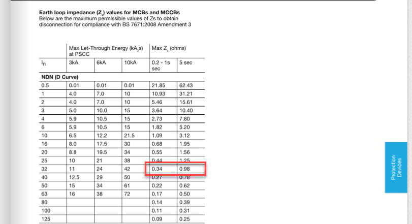
Common question: Why is the max Zs figure of a manufacturer-specific device different from the tables in BS 7671?
Answer: The max Zs is calculated using the time-current curves of the protective device. Generic and Manufacturer-specific devices may have different curves that may result in different Max Zs figures. The Max Zs tables in BS 7671 are based on the Generic curves as displayed in the Regulation. The example below shows the relevant max Zs figures when considering the Generic and Hager MCB device, type D, 32A.


Also Read
-
Power Factor Correction Calculations (Views: 8258)
-
Surge Protective Devices - SPD (Views: 6843)
-
Schneider NSX Reflex Tripping (Views: 2351)
-
Schneider Powerpact MCCB (Views: 2859)
-
Arc Fault Detection Devices - AFDD (Views: 6667)


