Announcements
ElectricalOM Update 2018.08.14.01
Tuesday, August 14, 2018
We have updated ElectricalOM to version 2018.08.14.01. In this version we have made lots of improvements and we implemented new features based on users' requests and feedback.
Some of the features of the new version are listed below:
1. Din Rail Levels
The designer is able to set the levels of a din rail distribution board. This provides more flexibility in representing the schematic diagram and enables printings in smaller page sizes. Any sub distribution circuits fed by the leveled distribution board will become un-tethered and the user will have to reposition them.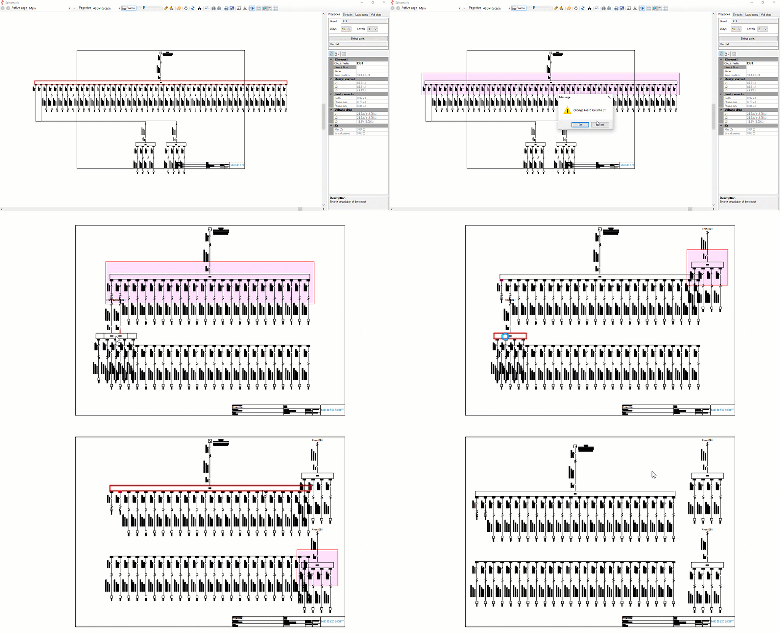
2. Din Rail Odd Ways Number
The user is now able to select an odd ways number for a din rail distribution board. Please note that this is available only to din-rail DBs. The vertical solid busbar distribution boards can only be set to an even ways number.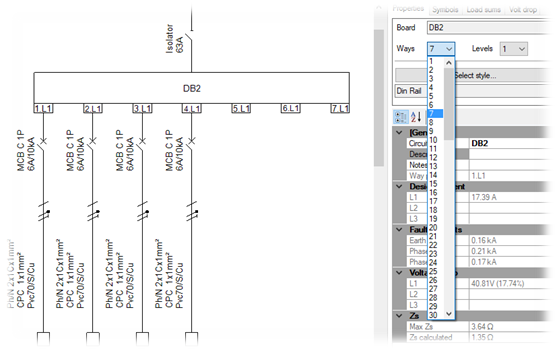
3. Lighting Columns Connection
A new lighting column connection is now available to enable the engineer to design street lighting arrangements. In each lighting column the user can install one or more lighting circuits and/or one or more lighting columns making possible the modeling of complex street lighting arrangements.
A video tutorial that demonstrates the street lighting functionality will be released shortly.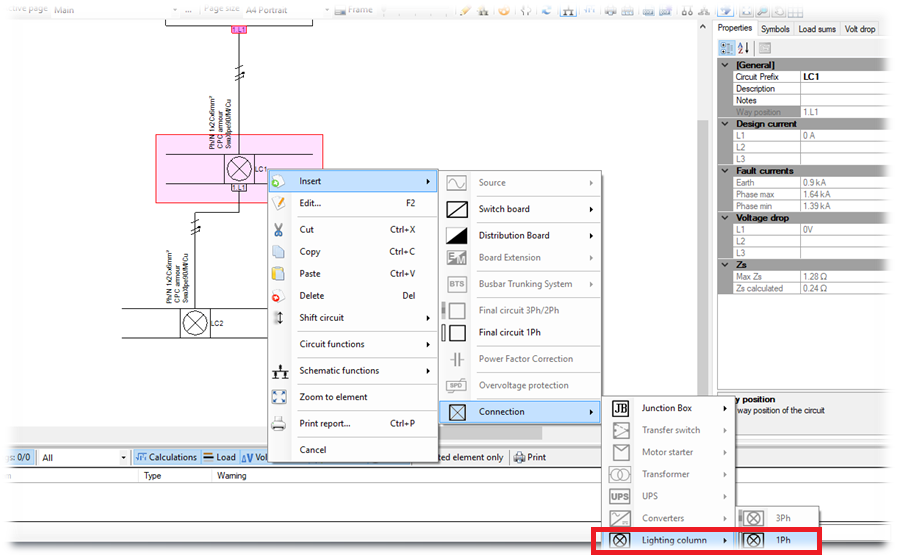
4. Lighting Columns Schedule Report
A new report has been added for printing the lighting columns schedule. The report lists the following information:
1. Circuits descriptions,
2. The cables used in between columns,
3. The cables used for connecting the column junction to the lighting,
4. The circuits design load,
5. The circuits voltage drop, also indicating the circuit with the highest voltage drop in the complete street lighting arrangement.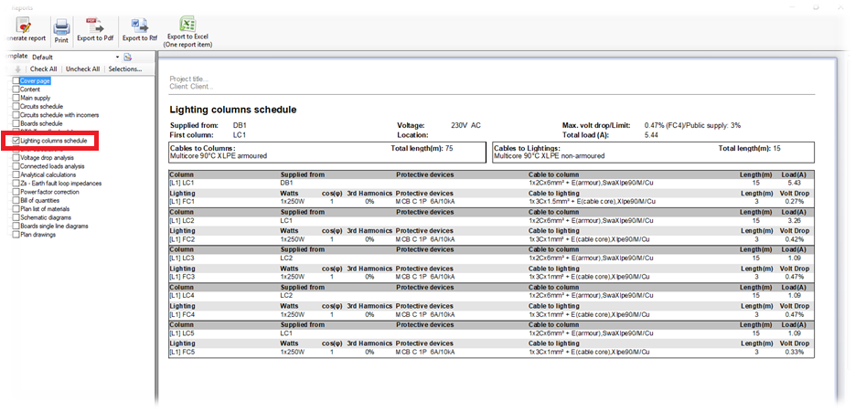
5. Over-voltage protective devices - Surge Protective Device (SPD)
A new option for installing an SPD device has been added. This will allow the engineer to install an SPD device and set the relevant parameters with appearance in the schematic for the representation of the over-voltage protective devices.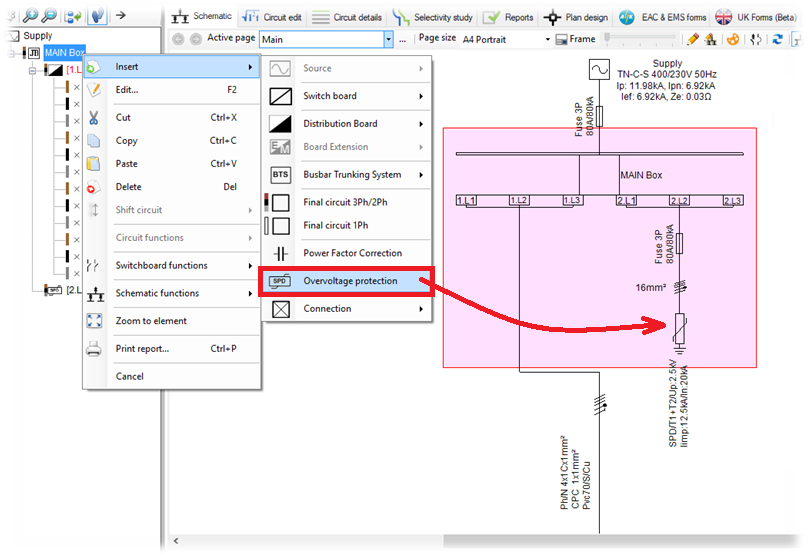
6. Surge Protective Device Checks
Whenever the user installs an SPD device the software will perform validation checks based on EN 62305-2 & BS 7671:2015 534.2.1.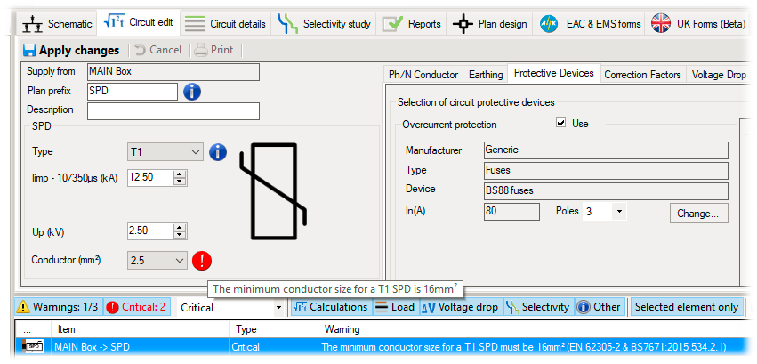
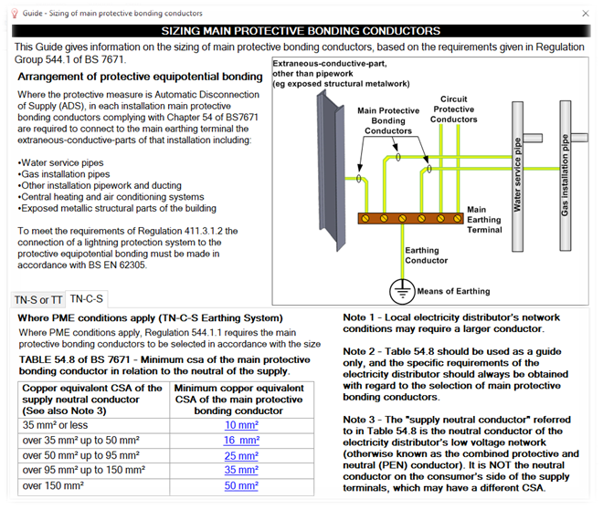
7. Main Bonding Conductor Guide
A guide related to the sizing of the Main Bonding Conductor has been created to help the engineer with the selection based on the regulation group 544.1 of BS 7671. A check is made and a warning is shown if the engineer chooses a value that violates the relevant regulations. The guide can be accessed in the main supply's "Other" tab page at the main bonding conductor selection.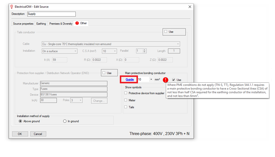
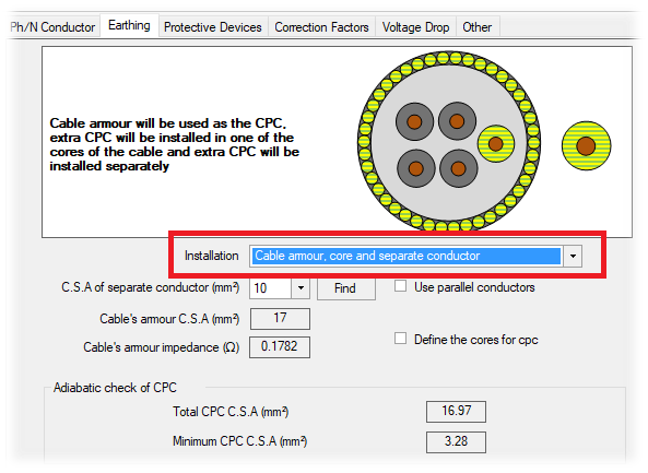
8. New CPC Option for Armour Cables
A new cpc option for armour cables has been added in the cpc installation list. This will allow designers to select the cpc as a combination of the armouring of the cable with an extra core of the cables plus a separate conductor.
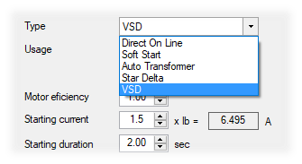
9. Variable Speed Drive (VSD) Motor Starter
In the motor types selection list we included the Variable Speed Drive (VSD) option.
10. Motor Starters Symbols
The symbol of a motor starter connection is now based on the motor starter type selection. The relevant motor starter symbol will be updated in the schematic to reflect the starter type selection.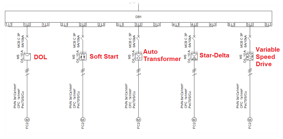
11. Harmonised European standard cables
A new cable standard option "EN" has been added for the selection of Harmonised European standard cables.
12. CAD Plan design additions
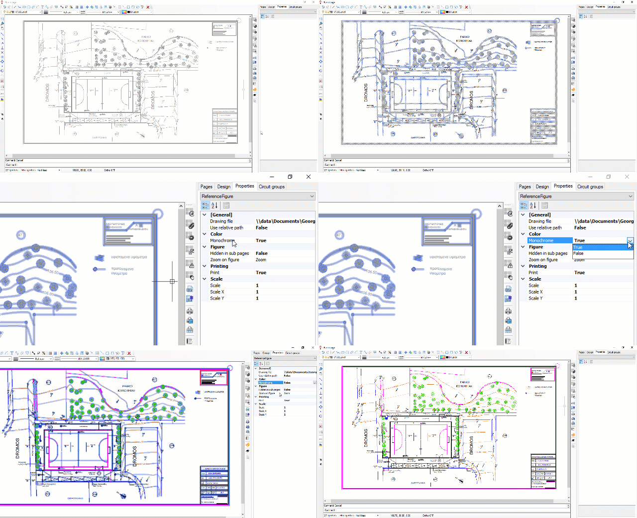
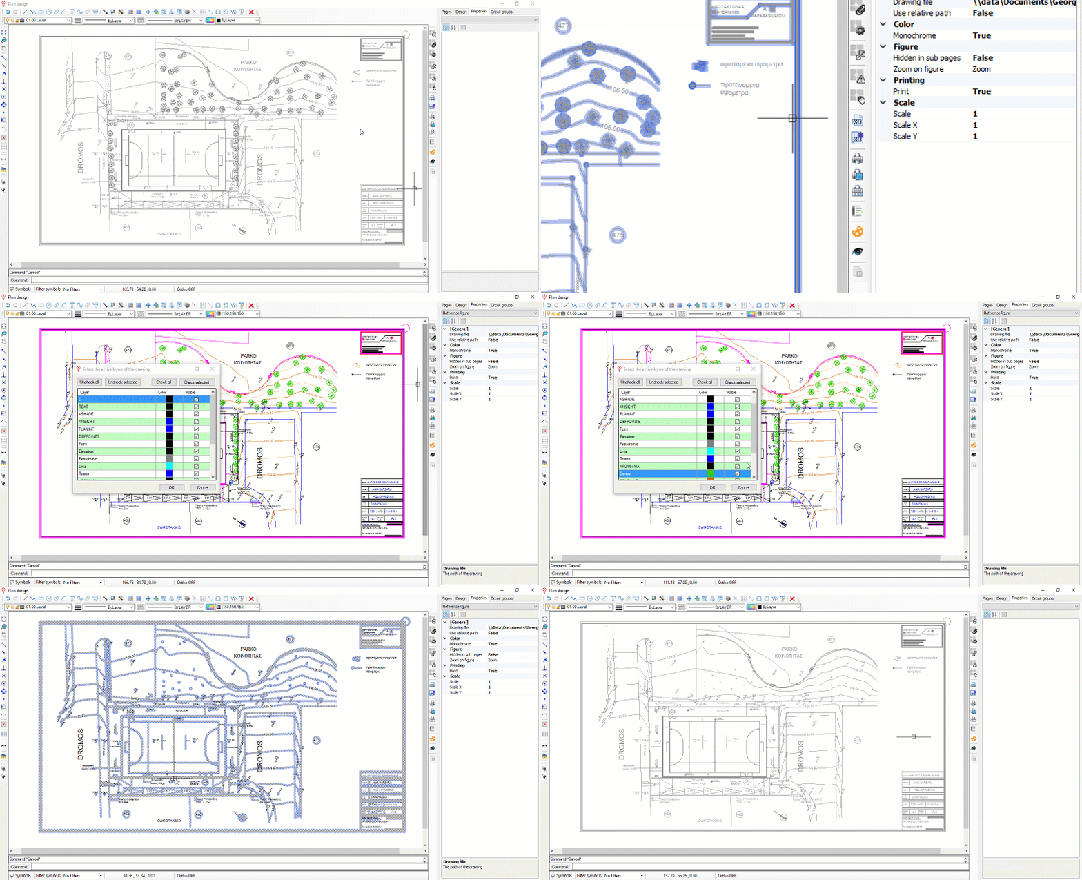
XRef Monochrome Property
By default this property is set to True meaning that the reference drawing is appearing with a single color. If the property is turned to False then the original colors of the drawing will be presented.
XRef Layers Colors and Quick Selection
During the Xref layers visibility selection the user can see the colors of the relevant drawing layer and quickly select them by clicking a figure in the reference drawing.
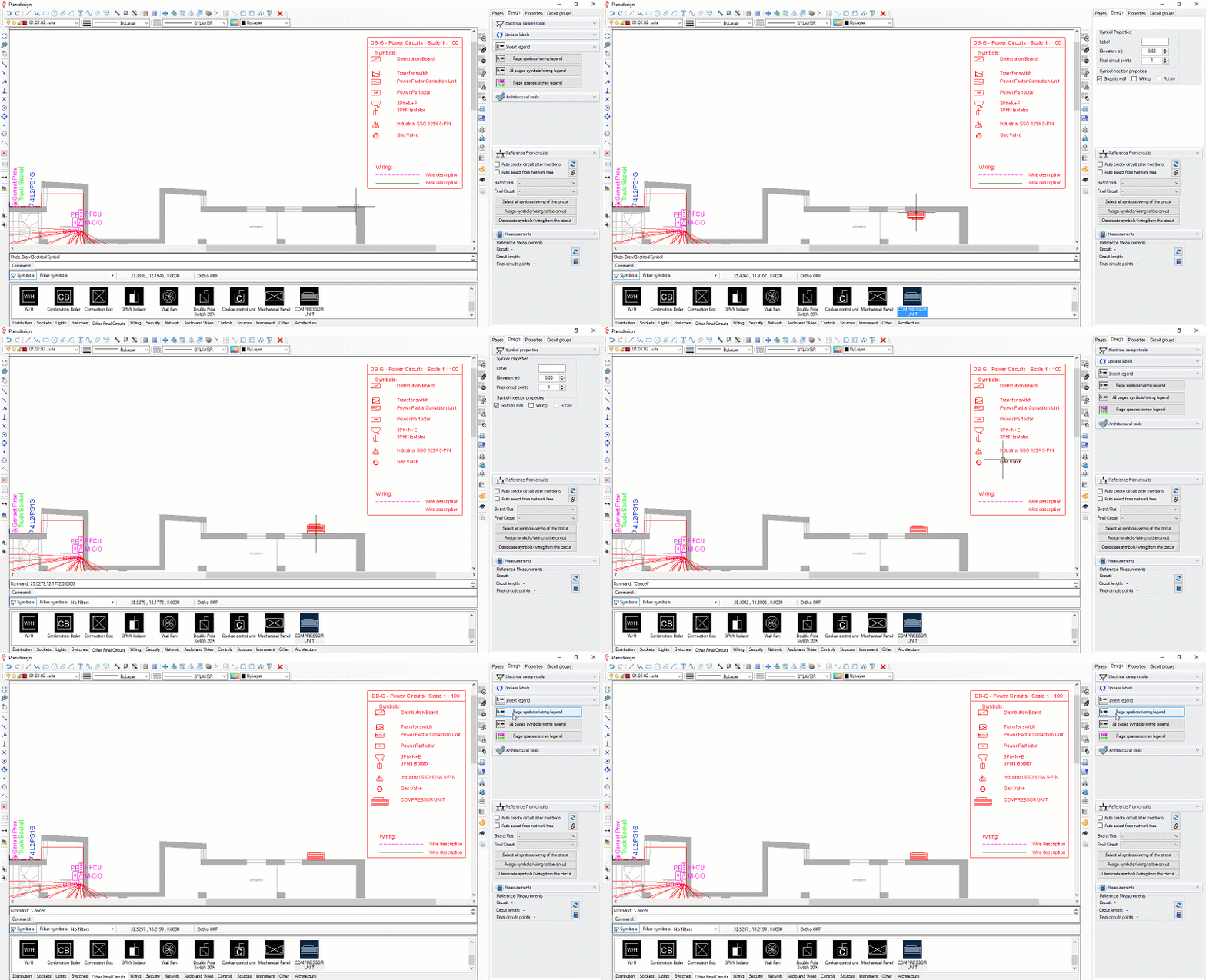
Dynamic Symbols Legend
The legend is dynamically updated with insertion or deletion of symbols in the drawing and there is no need to reposition it.
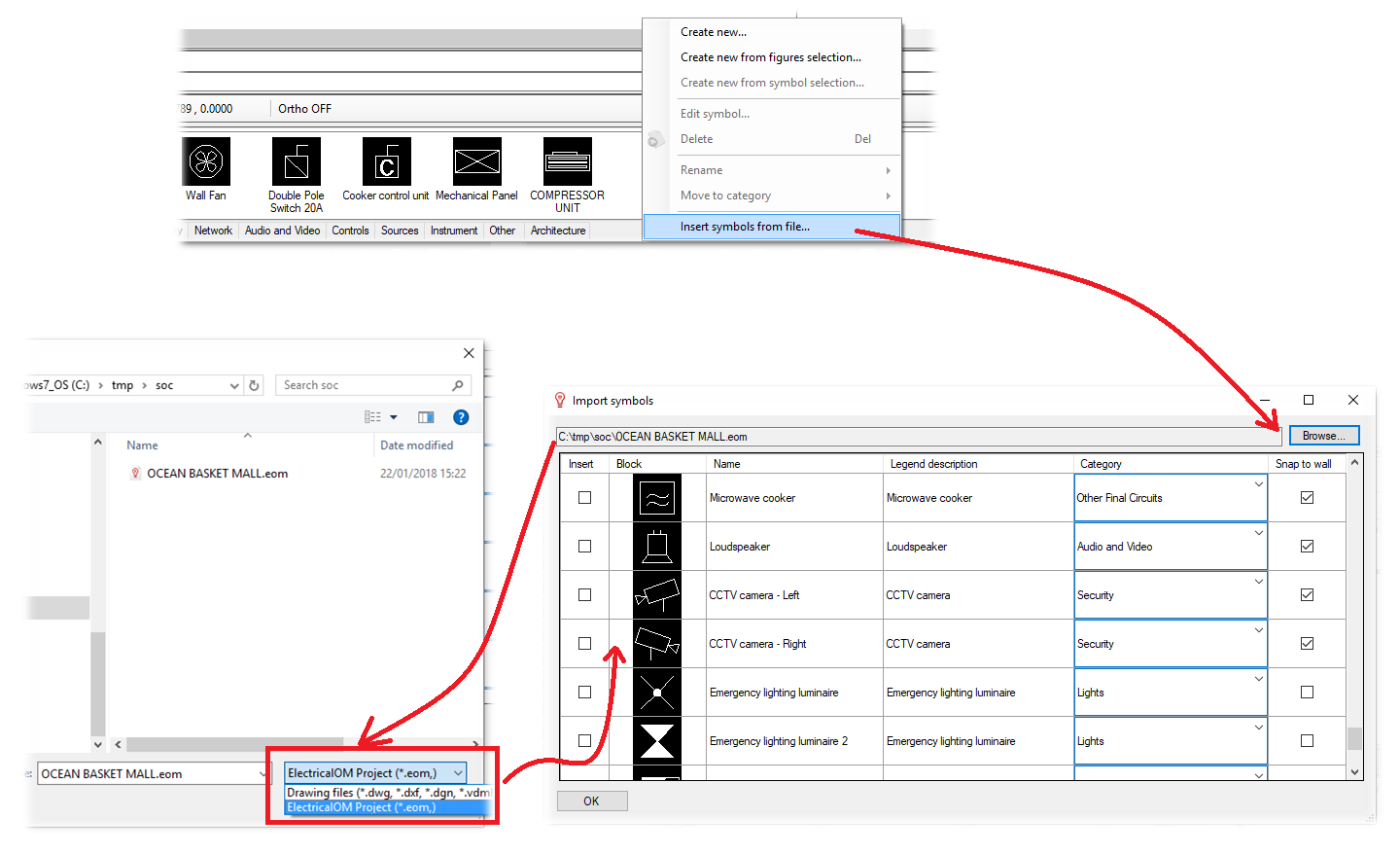
13. Insert Symbols From Existing ElectricalOM Project
Users can now share symbols from an existing ElectricalOM project using the "Insert symbols from file..." functionality accessed by right clicking on the symbols area. After pressing the "Browse..." button, change the file type to ElectricalOM Project (*.eom), select the appropriate project file, and all symbols used in the project will be automatically populated and will be assigned with all relevant properties.
14. New Protective Devices Added
In the new version we included new protective devices from several manufacturers (CONTACTUM, HYUNDAI).


