Announcements
ElectricalOM Update 2018.01.28.01
Monday, January 29, 2018
We have updated ElectricalOM to version 2018.01.28.01. This version includes many new features based on users requests and feedback.
Some of the features of the new version are listed below:
1. DC Cable Sizing Calculations
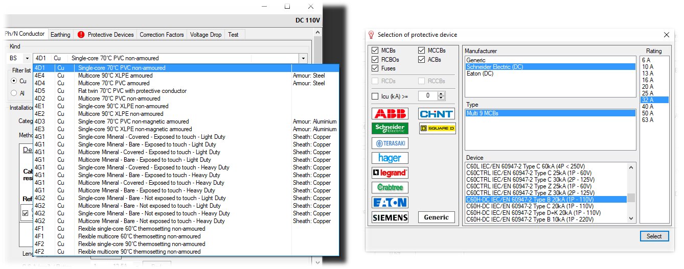
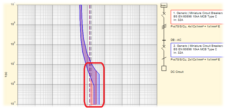
We have included the BS7671 DC cables data in the cables library for DC cable sizing calculations. Now, when designing in DC, the software will automatically populate the DC cables in the cables list. The absence of natural voltage zero makes the interruption of DC faults more difficult than the interruption of AC faults, and for this we have included DC protective devices from various manufacturers. Moreover, in cases where some manufacturers state that their alternating current equipment can be used under direct current, we are making use of the Variation of the Magnetic Tripping Coefficient (Ikm). This is to accommodate the instantaneous tripping that occurs at a different value than it would under alternating current
2. Variation of the Magnetic Tripping Coefficient (Ikm)
The Ikm coefficient, variable as a function of the circuit breaker and of the connection type of its poles, allows to derive the DC instantaneous trip threshold starting from the relevant value in alternating current. This coefficient will be available when selecting AC devices under DC. It is highly recommended to get advice from the manufacturer's specifications when using this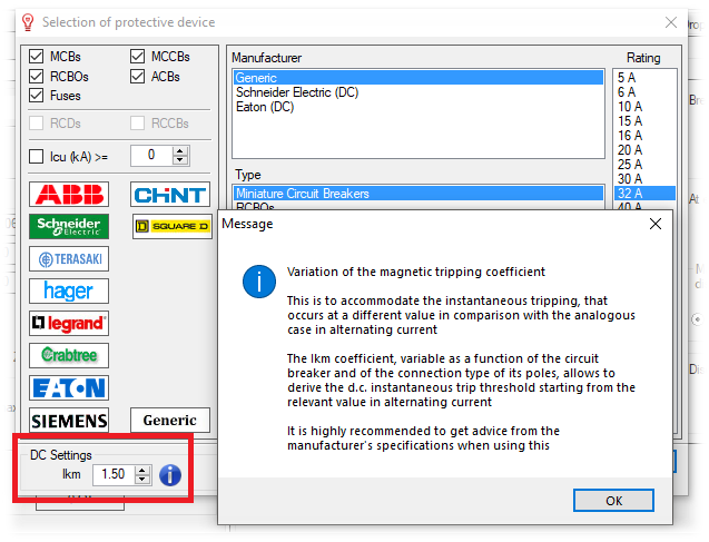
3. DC Battery Source
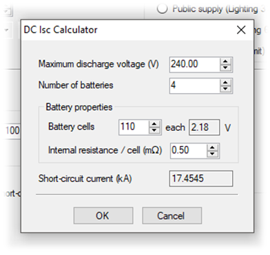
A DC battery source can now be used to set the installation conditions at the origin in order to model a direct current network. A fault level calculation environment has been developed to help the engineer quickly calculate the fault level at the battery output by specifying some parameters related to the battery source arrangement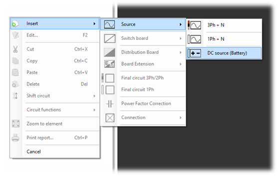
4. Rectifier Connection (AC to DC Conversion)
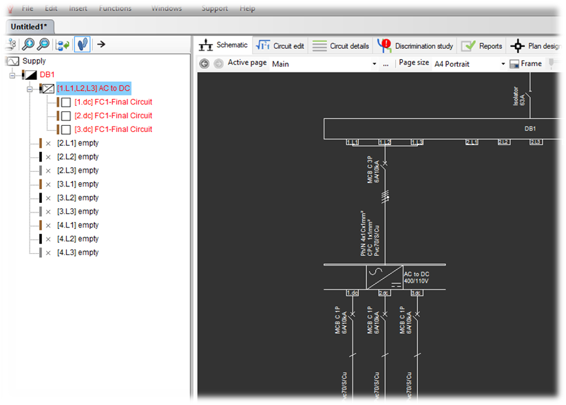
The rectifier connection will enable the designer to implement AC and DC networks in the same project. Any circuit fed by a rectifier connection will be simulated in DC. At the rectifier editor the user can set the voltage and fault level at the DC side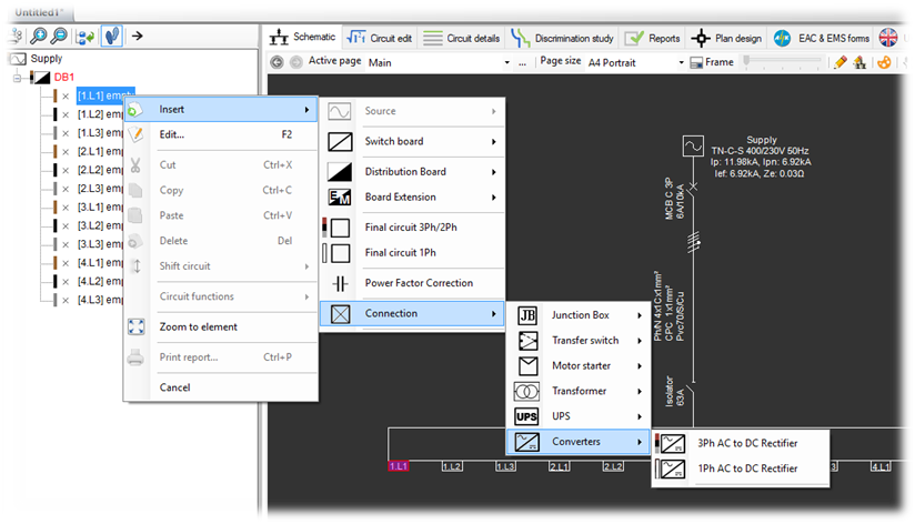
5. Electric Vehicles Charger
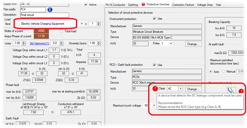
The Electric Vehicles Charger is now listed in the final circuit load types. When selecting the Electric Vehicles Charger type the software will indicate a warning for using class A or B RCD device that can identify DC current leakage
6. IT Earthing System Option
The IT Earthing system option is being added to the Main Source Editor. This will perform the necessary checks for the second fault occurring in an IT system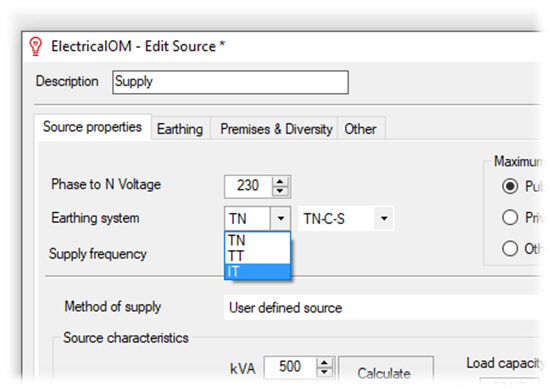
7. Select Boards and Schematic Pages to be Included when Generating the Reports
This feature enables the engineer to generate reports, selecting only the desired boards and/or schematic pages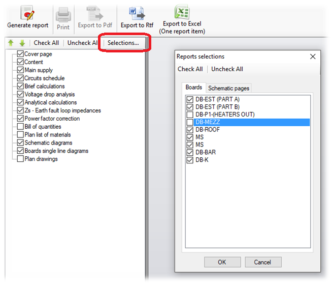
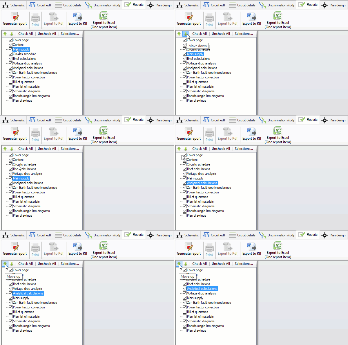
8. Reorder the sections in Report
This will allow the user to change the order of the sections before generating the report
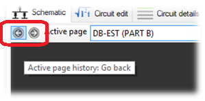
9. Quick Page Navigation in Schematics
This functionality enables the user to quickly navigate (Back/Forward) through the pages selection history
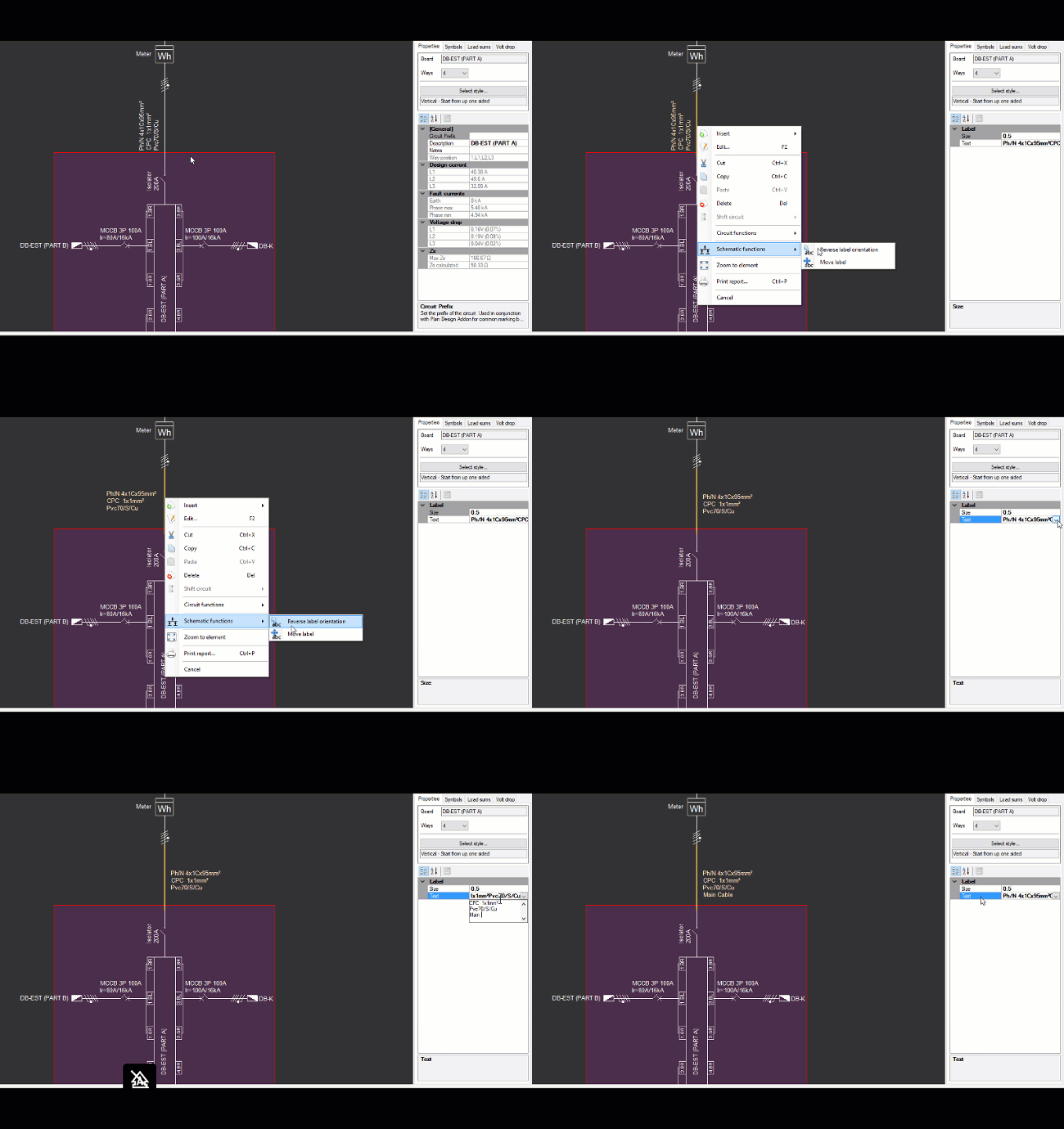
10. Ability to Modify Cable Labels in Schematic
Like symbols, the designer can now modify the cable’s label position, orientation, text and size
11. Auto Symbol in Main Source
From the supply editor the user can now choose to display the protective device from supplier (DNO), the meter at the origin of the installation and tails conductor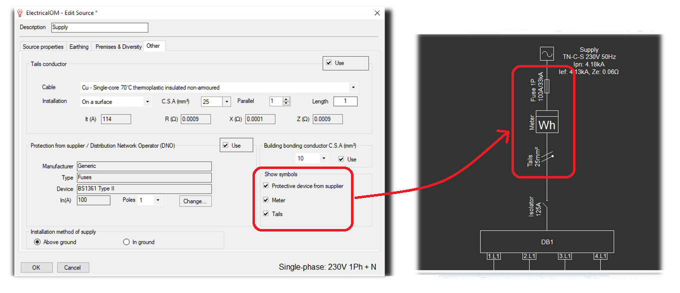
12. Ability Not to Use the Feeder Conductor of a DB Circuit
This is to allow precise modeling of main consumer units in TT systems, when the part of the installation between the origin and the device (RCD in the consumer unit) complies with the requirements for the protection by the use of class II equipment or equivalent insulation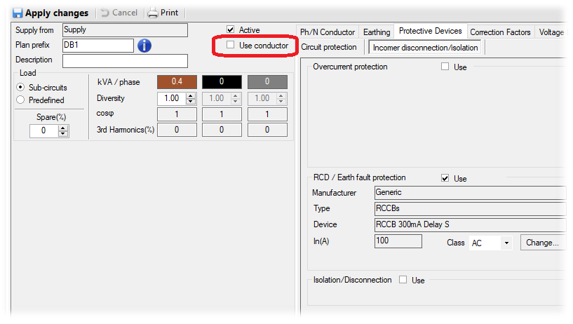
13. Plan Design Add-on:
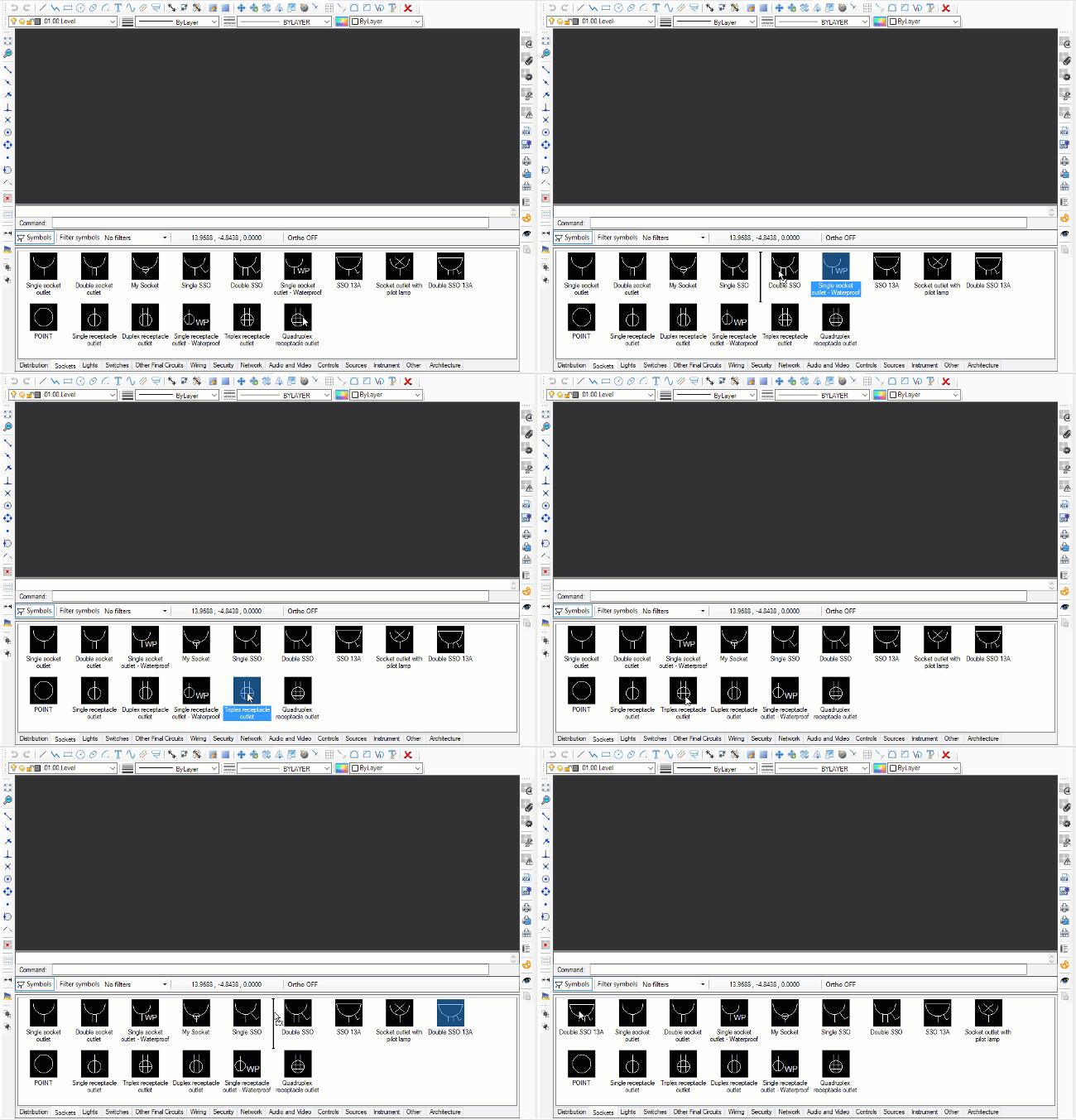
13.1 Symbols library rearrangement
The user can now rearrange the position of the symbols in each category
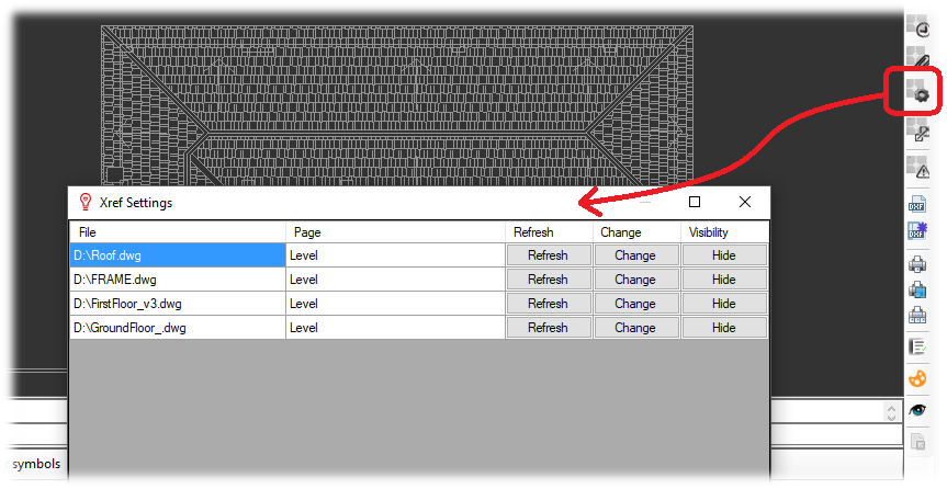
13.2 Updated Xref settings environment
We updated the Xref settings environment to allow the user reload, change or show/hide an external reference file
13.3 Xref drop
The user can now insert an external reference drawing or pdf by dragging and dropping it directly to the drawing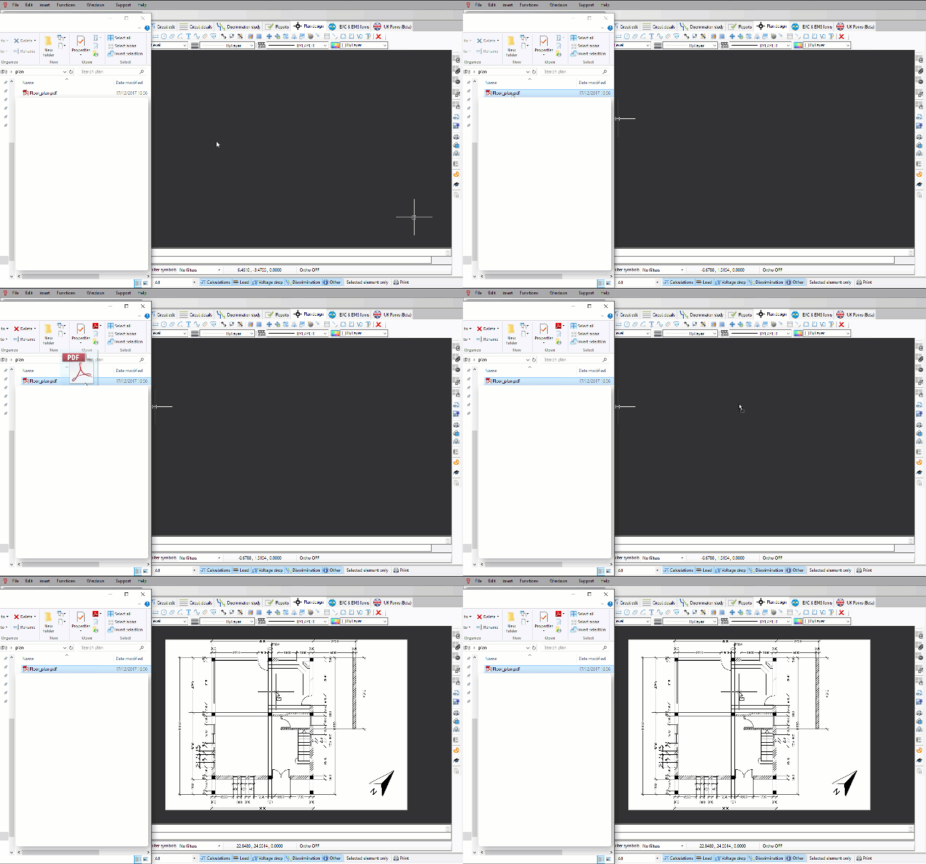
14. Protective Devices:
14.1 DC Devices
Eaton Bussman Fuses
Schneider Electric DC MCBs
14.2 AC Devices
14.2.1 EATON
Memshield 3 MCBs
Memshield 3 RCBOs
NZM MCCBs
Series G MCCBs (Thermo-Magnetic trip)
Series G MCCBs + Digitrip (Electronic trip)
Mangum ACBs
Industrial Fuses
14.2.2 Chint
NB1 MCB
NB1L RCBOs
14.2.3 SquareD
KQ MCBs and RCBOs


