Announcements
ElectricalOM Update 2017.06.27.02
Tuesday, June 27, 2017
We have updated ElectricalOM to version 2017.06.27.02.
Some of the features of the new version are listed below:
1. Plan design additions
1.1 Auto insert and associate circuit from symbols insertions
Automate the creation of the schematic diagram while inserting plan design symbols.
Step 1: Insert the symbol. Before insertion check the option "Auto create circuits after insetions".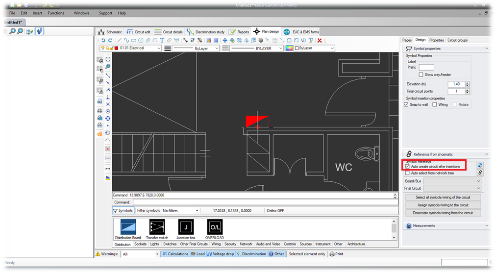
Step 2: Set the circuit parameters.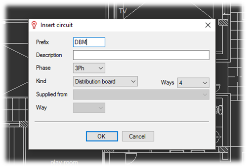
Result: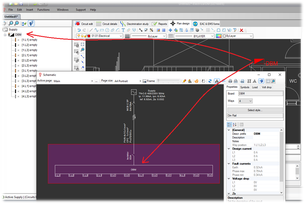
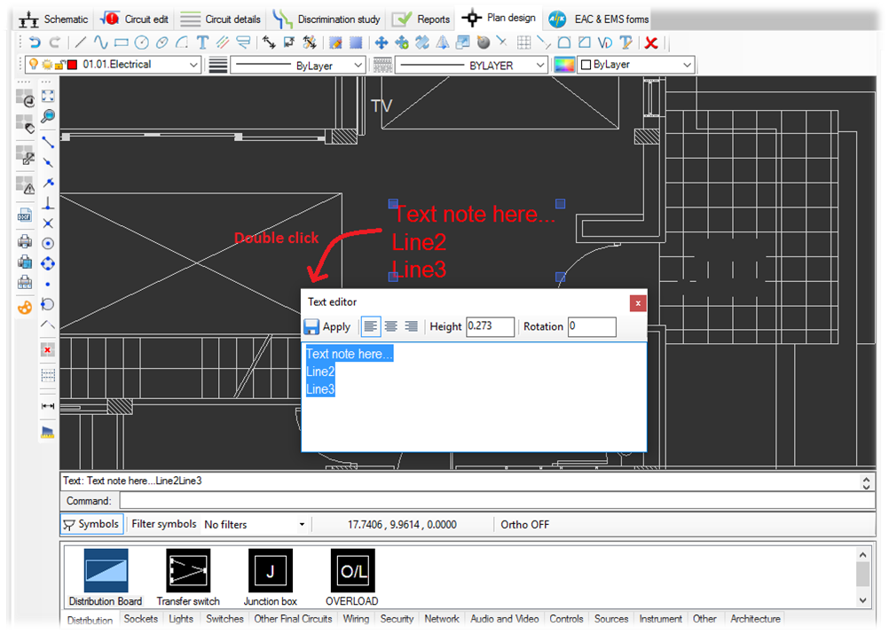
1.2 Quick text editor
Easily edit the text by double clicking on the text figure.
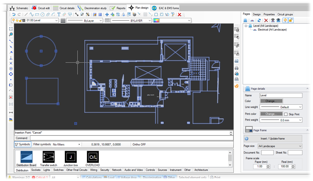
1.3 Plan design environment improvements
We have update some parts of the plan design environment to make it more user friendly and intuitive. In particular the improved environment includes:
- Customizable tools strips
- Grouped functions
- Selections highlight and Selections grips visibility
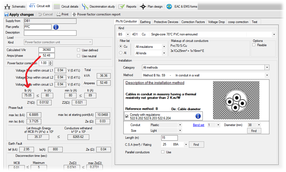
2. Power factor correction unit cable sizing in accordance with IEC 60831-1 and IEC 60931-1
Extra considerations are now been made when calculating the design current for the Power factor correction units, in order to comply with IEC 60831-1 and IEC 60931-1. In particular based on the above standards the Power factor correction capacitors shall be able to operate under steady-state conditions with an r.m.s. current value up to 30% higher than their rated current (this is due to the possible presence of voltage harmonics in the network). Also, the above standards specify that a tolerance of +10% on the capacitance shall be admitted. Therefore, a capacitor bank can absorb a maximum current of: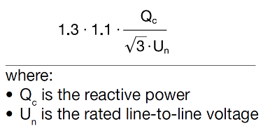
3. Notes on schematic description label
Notes on schematic allow the user to insert extra text below the element's description. This can be done from the properties area as shown below: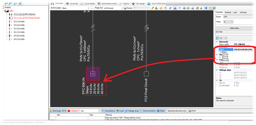
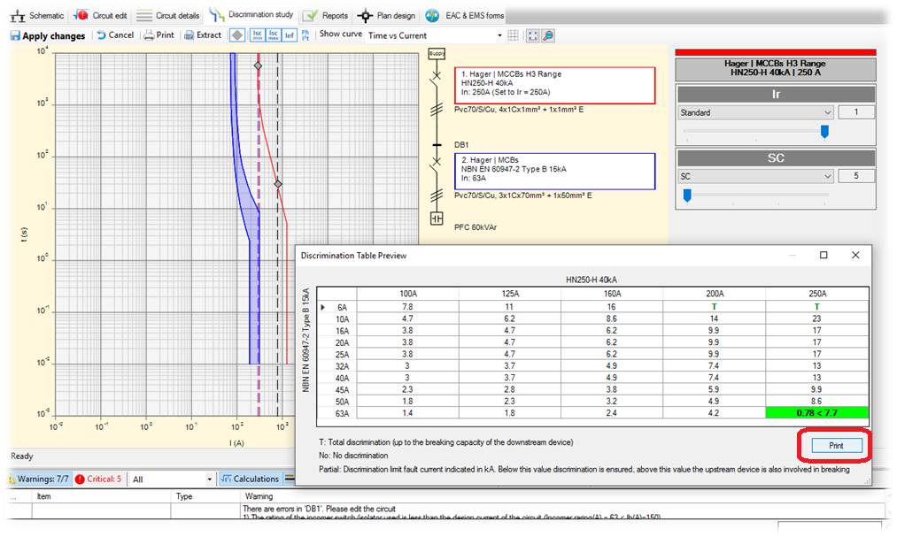
4. Print discrimination table preview
The user can now print the discrimination table used when performing discrimination checks.
5. Protective devices library additions
- Hager H3 MCCBs
- Hager RCBOs
- Terasaki TemBreak2 MCCBs
- Terasaki TemPower ACBs
- Terasaki RCBOs
- Cabrtree RCBOs


