Announcements
ElectricalOM Update 2017.05.16.07
Wednesday, May 17, 2017
We have updated ElectricalOM to version 2017.05.16.07.
Some of the features of the new version are listed below:
1. Drawing mode on entity
Figures on entities are attached to the schematic element meaning that they will be transformed, moved, copied and rotated according to the behavior of the schematic element. Watch the video below for a quick demonstration of this function.
2. Parallel UPS operation
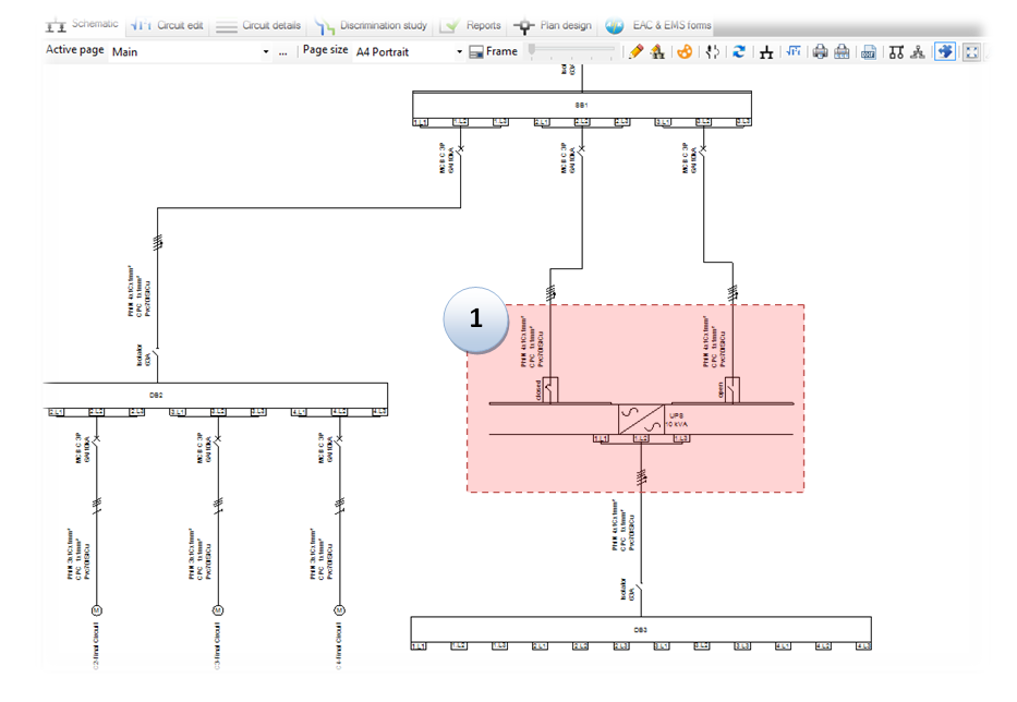
Like parallel sources the engineer can choose to set a UPS to operate in parallel. This can be done on a UPS with multiple feeders from the same supply.
Follow the steps bellow to set the UPS in parallel operation:
Step 1: Add the UPS with multible feeders from the same distribution circuit.
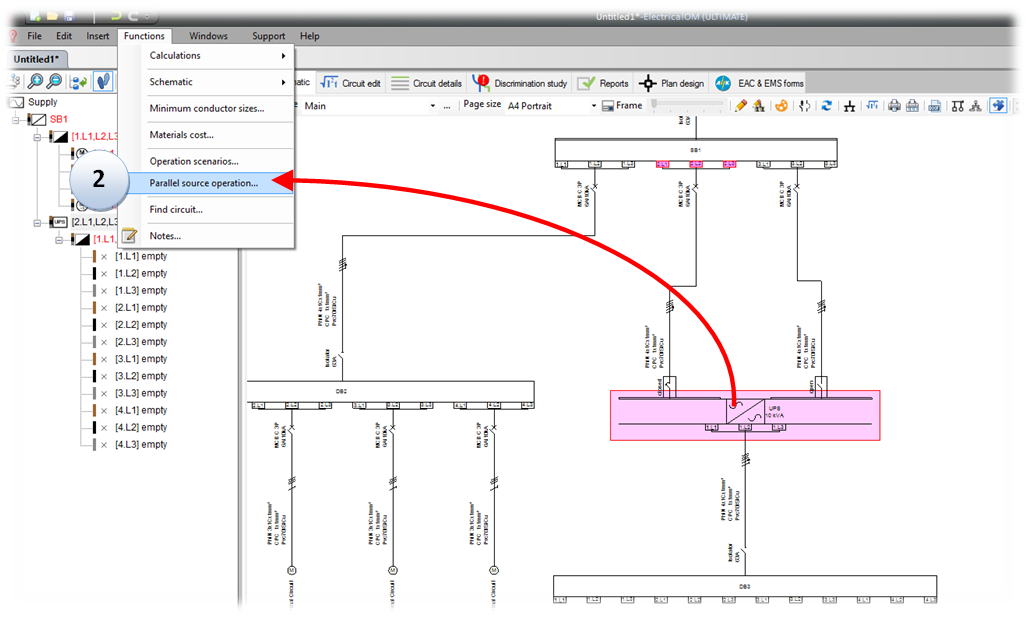
Step 2: Select the UPS and choose "Parallel source operation..." from the main menu under Functions.
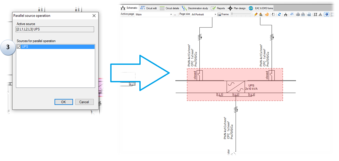
Step 3: Select the UPS from the list and press OK. The UPS feeders are closed and the UPS rating is multiplied based on the number of parallel sources.
 3. Flexible Cables
Extensive list of flexible cables has been added to the new version, based on BS 7671 tables.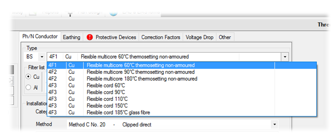
4. Plan prefix for circuits
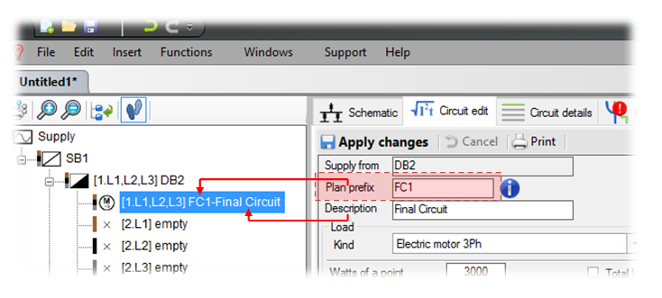
The resulting description of a circuit is now based on the plan prefix annotation and the circuit description. This is used in conjunction with the plan design addon for common marking between the circuits and the plan symbols. See the plan design additions below for more details.
5. Plan design module additions
The plan design addon has been enriched with new functionalities and improvements. The major additions are listed below:
5.1 Enhanced design menu
From the design menu the user can quickly select the most common used design functions or choose to repeat the last action. The design menu is accessed through right clicking the design area.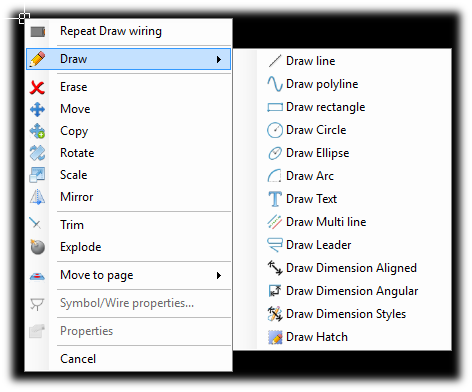
5.2 Move to page (layer)
From the design menu the user can choose to change the page (layer) of the selected figures.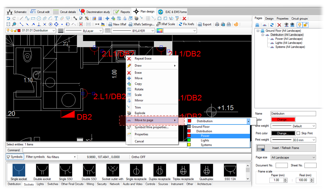
5.3 Show prefix/way/feeder on symbol
To keep consistency between the schematic circuits and the plan symbols the user can choose to show the prefix/way/feeder on each symbol that has been associated to a circuit.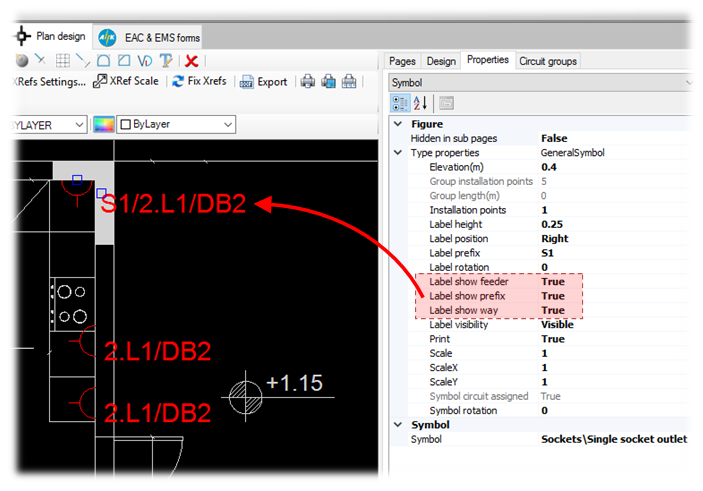
5.4 Consistency between circuit description and symbols label
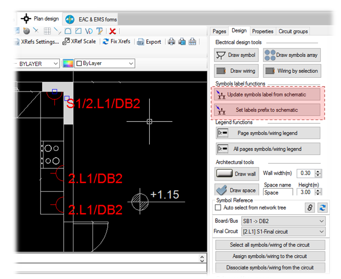
To keep consistency between the circuit description and the plan symbols label we have introduced the circuit prefix property. The value of this property can be assigned during the circuit editing or from the plan design by modyfing the symbol's label prefix property. After a modification the user can choose to update the label of the assigned symbols or the circuit prefix by choosing one of the functions below:
Update symbols label from schematic circuit
With this function all the symbols that are associated to circuits will update their label based on the circuit (prefix, way, feeder).
Set labels prefix to schematic
With this function all the prefixes of the schematic circuits will be updated based on the associated symbols label.