Transformer
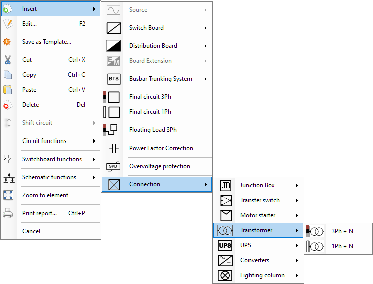
Transformer component is used to model a transformer and it has two versions as 3Ph + N and 1Ph + N. A transformer cannot be inserted after a Source, it needs a distribution node to get connected. Multiple Sources feature is also applicable for junction boxes, refer to this section for more information about multiple sources.
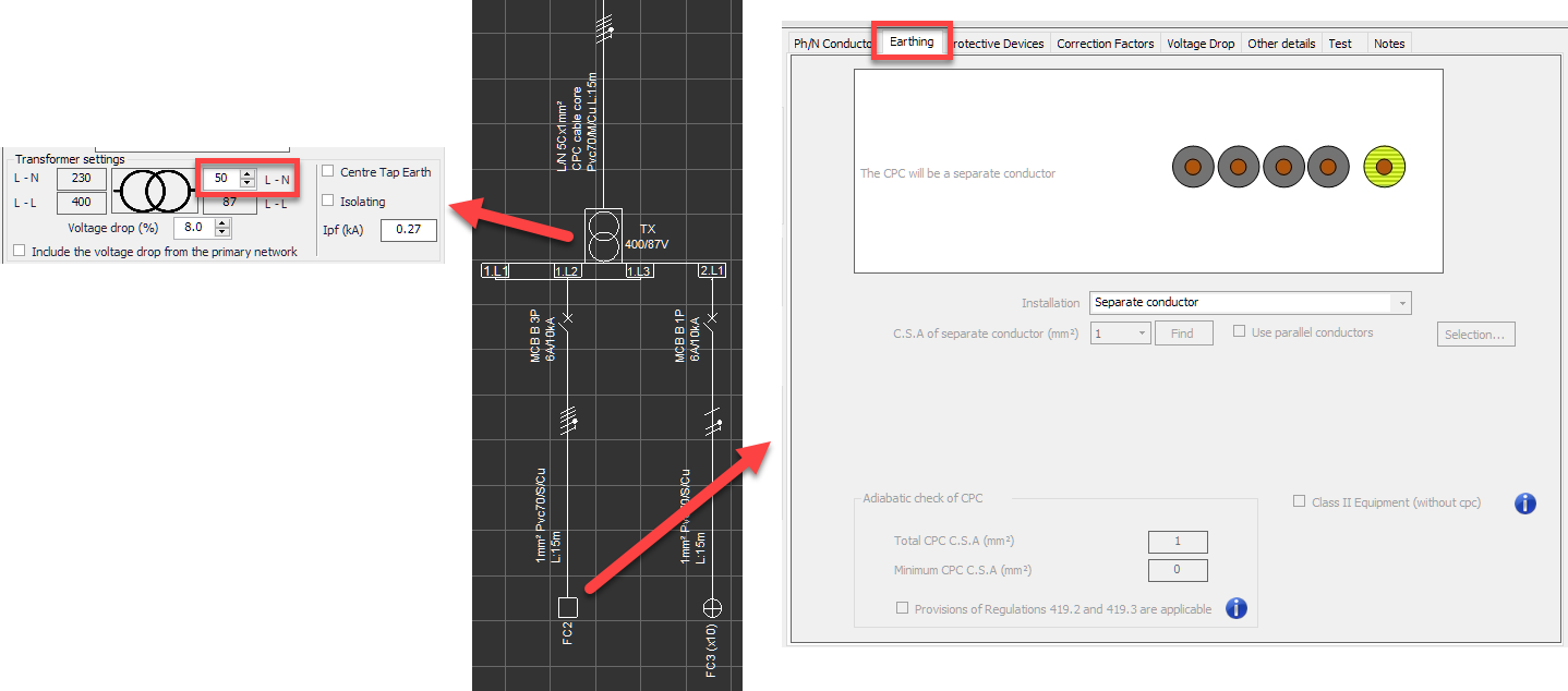
Circuit edit tab of a transformer has a Transformer settings section instead of a Load section, where the user can define various parameters. Also, a Settgins button is available for fine tuning the transformer parameters.
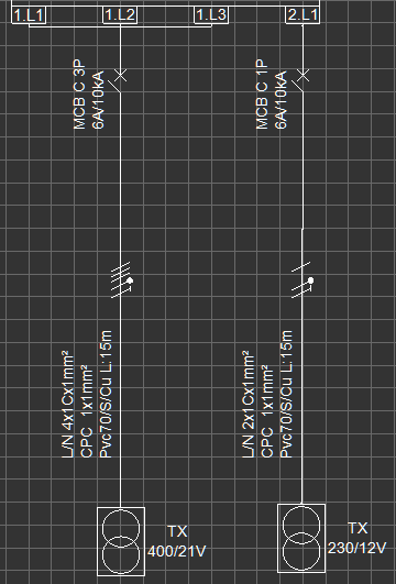
L-N voltage: This text field can be typed in by the user to define the voltage between the Line and Neutral conductors of the transformer on the secondary side. If the transformer is a three-phase transformer, then, ElectricalOM will calculate the secondary L-L voltage automatically using this value.
If the secondary side voltage is below or equal to 50V, then, ElectricalOM will consider an ELV circuit and the Earth Fault section will be replaced by an new section, ELV System, at the calculation area for any downstream circuit.
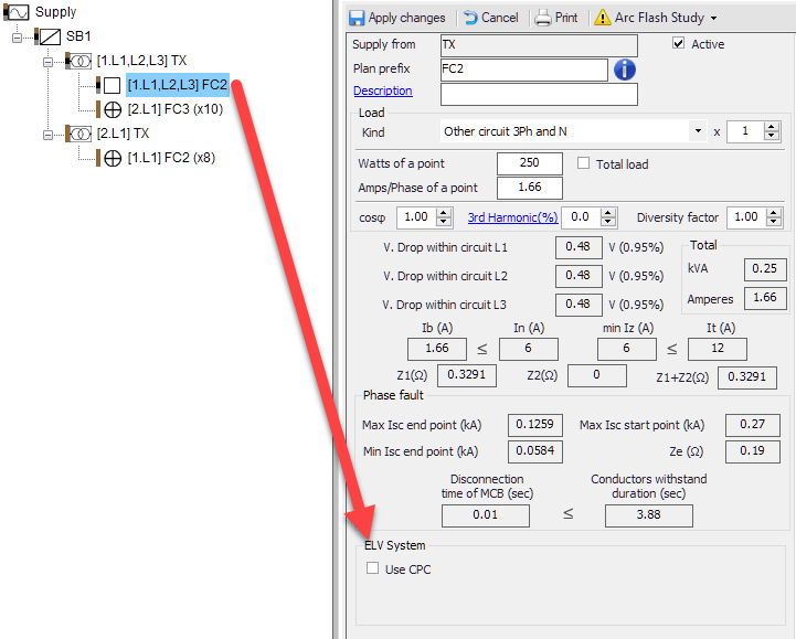
Additionally, and the Earthing tab of Circuit edit module for any downstream circuit will be disabled by default.
If the user opts to use a CPC for an ELV circuit, then ticking the Use CPC tick box will enable the earthing conductor option at the Earthing tab.

Centre Tap Earth tick box: If this box is ticked, then, ElectrcialOM will assume the secondary winding of the transformer is connected to earth potential at the mid point. As a consequence, the operating voltage on the secondary side will be halved.
Isolating tick box: This tick box will set the transformer as an isolation transformer and removes the connection to earth on the secondary side.
Ipf (kA): This field is used to define the prospective fault current on the secondary side.
VD Limit (%): This field denotes the voltage drop level permissible after the transformer in percent. The global voltage drop limit (see Source properties Tab section) will be applicable up to the incomer side of the transformer, where transformer's voltage drop setting will be applicable to any downstream circuits.