Middle toolbar
Middle toolbar consists of:
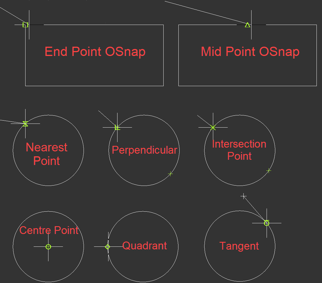
- OSnap Options (End Point/Mid Point/Nearest Point/Perpendicular/Intersection/Centre Point/Quadrant/Node/Tangent/Extension): OSnap feature helps the user to select specific points of objects by moving the mouse cursor to specified point automatically when the muse cursor is close. This action will be highlighted with a different green shape (triangle for mid pint, for example) by ElectricalOM. When the green shape appears, left mouse button will select the related point of an object. Each OSnap button will act like a toggle buttons and will stay active until they are disabled with a second mouse click.
- Ortho Mode: Ortho mode will let the user to move in orthogonal directions only. This way it is easier to draw straight lines.
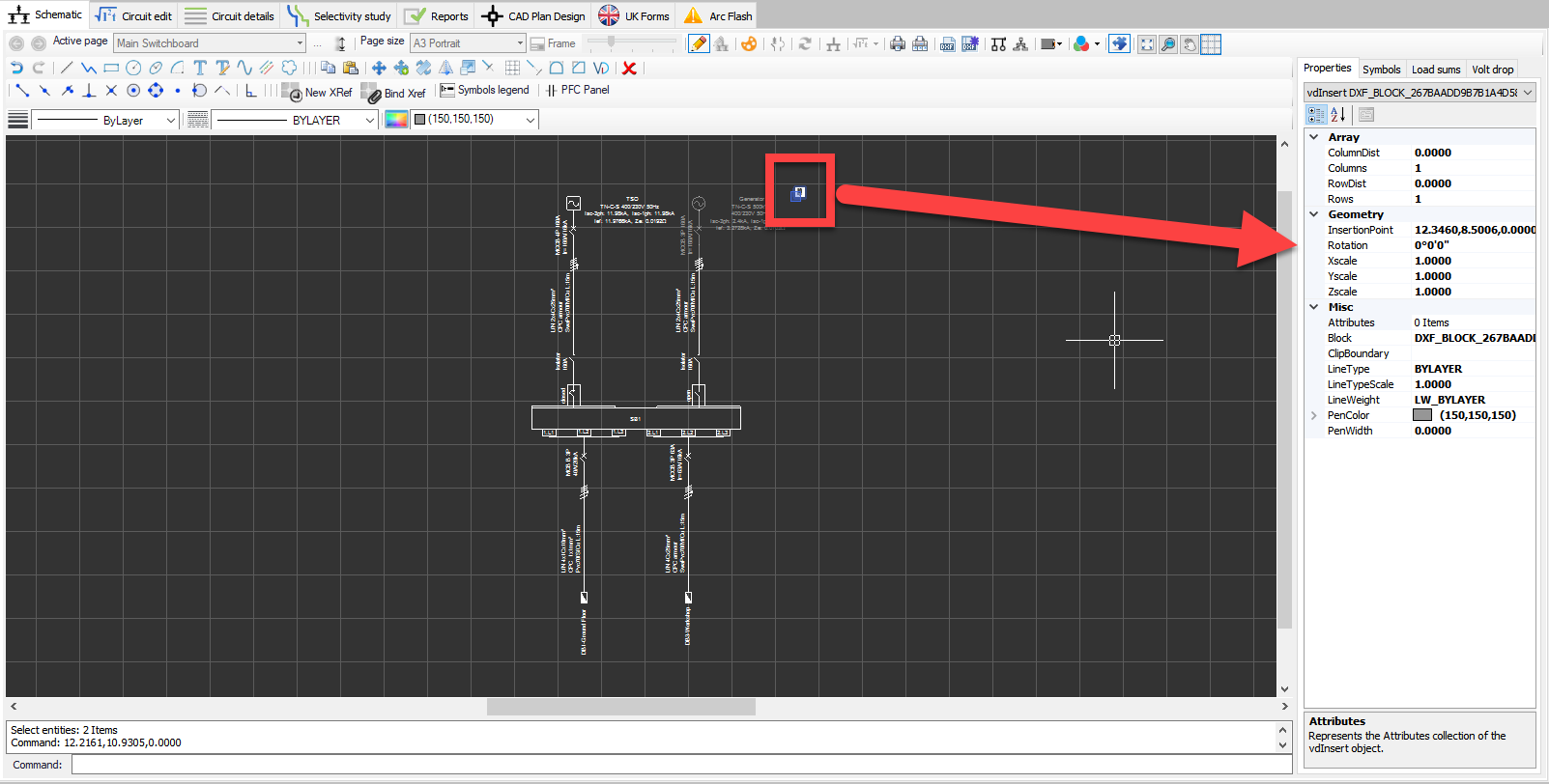
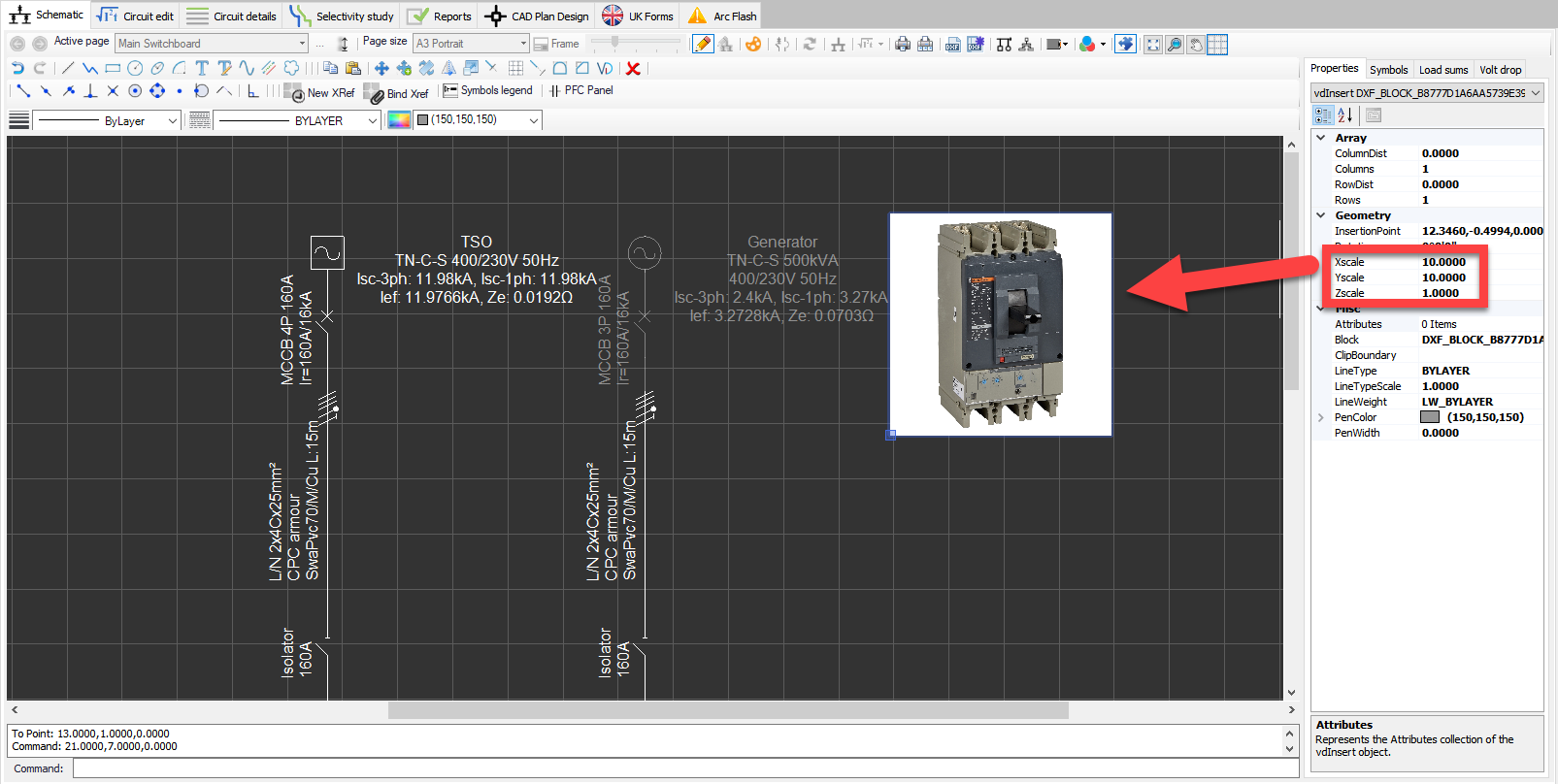
- XRef Options (New/Bind): ElectrcialOM lets the user to place external references to the schematics. In order to do this, the user must select an external reference by clicking on New Xref button. This will initiate the Xref file browser where the use can browse and select the external reference document to insert to the schematics. Once the XRef is selected, ElectricalOM will place it n the schematic, and when selected, side panel will display data related with it. The user can manipulate any property as required, for example, the scale (X, Y, and Z separately).
Supported file type are:
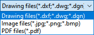
XRef still maintains the link to the original file, so, if the original file is missing, then the XRef within the ElectrciualOM will also disappear. Binding the XRef will remove the link with the original file and converts the XRef to a geometry within the ElectricalOM itself. Bind XRef button is used for this purpose.
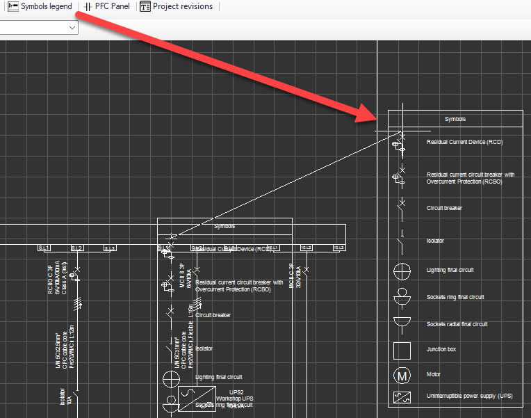
- Symbols Legend: ElectricalOM has a facility to create a legend for the symbols used on the active sheet automatically. In order to create the legend, Symbols legend button can be used. Once clicked, the mouse cursor will show the created legend and will wait the user to pick a location for the it. If the user wants to move or delete the legend, the Drawing mode must be enabled.
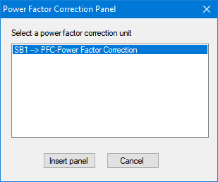
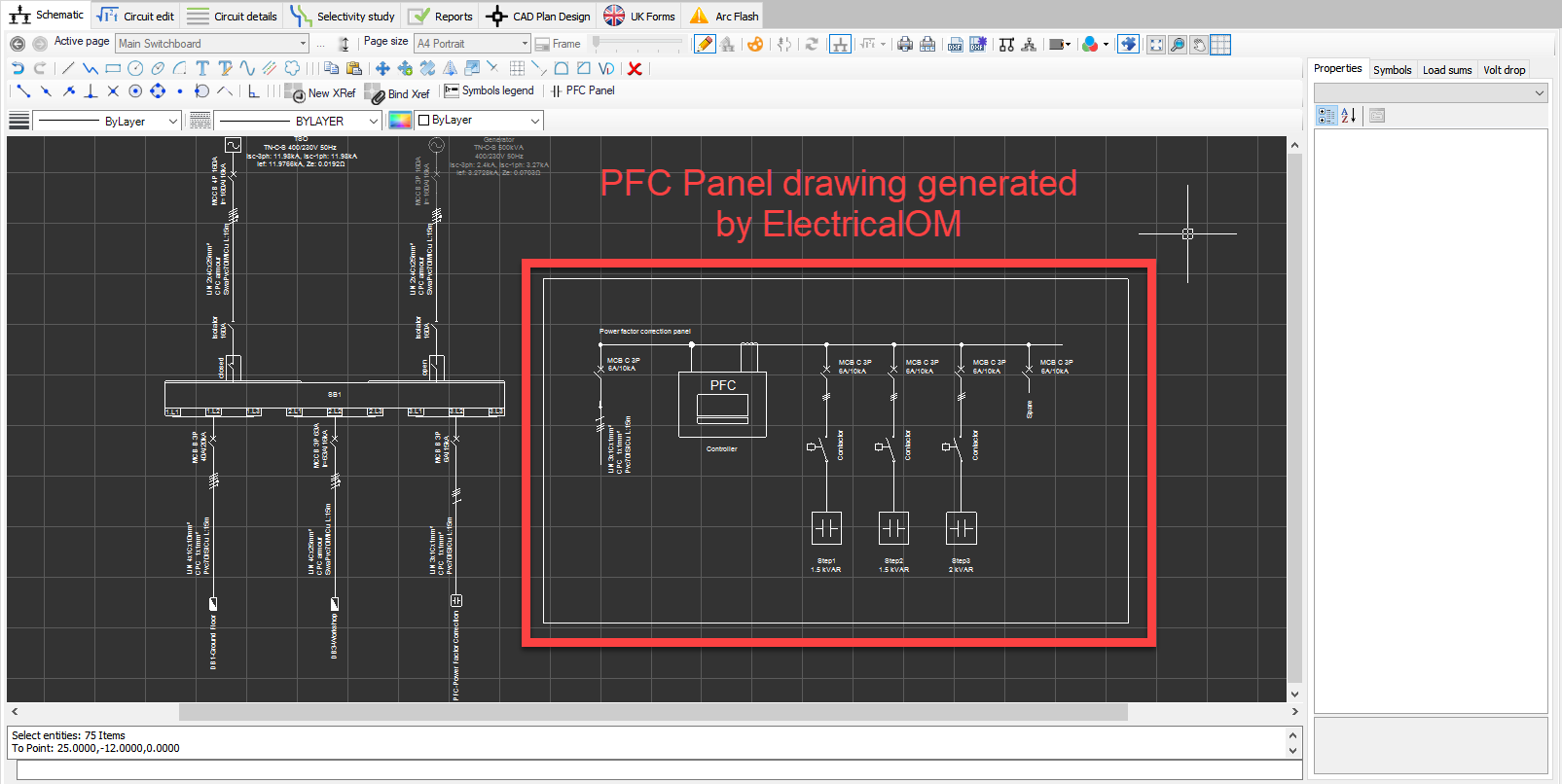
- PFC Panel: Sometimes a power factor correction system is needed due to a lower power factor value. When the user wants to insert a brief PFC panel drawing, PFC Panel button is very useful. The button will initiate the Power Factor Correction Panel window and will ask the user to select a PFC panel which has to be on the drawing already. After the user selects the PFC panel, ElectricalOM will generate the drawing and wait for the user to select a location for it. To modify or delete the drawing, the Drawing Mode must be enabled.
ElectricalOM will use data from Cosϕ Correction tab of the Circuit Edit module to generate the drawing.
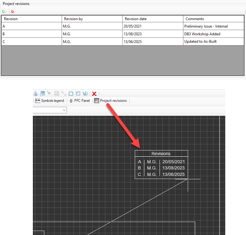
- Project revisions: User can inset project revisions table using this button. Information will be pulled from Project and info options.. menu.
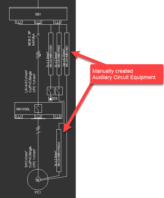
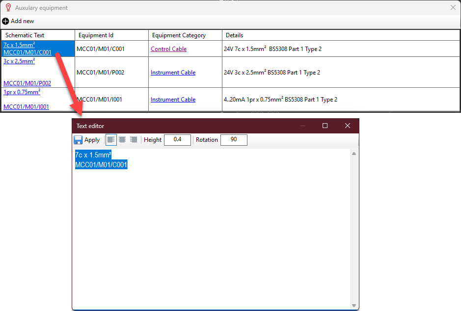
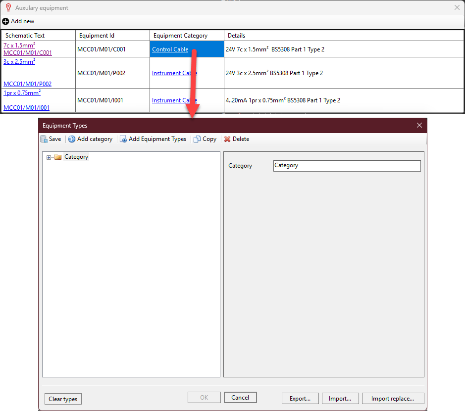
- Auxiliary circuit equipment: This option is only available within Manual Drawing Mode on Entity. It can be used to add control circuitry to the schematic. When this button is clicked on, it will initiate Auxiliary equipment window. Add new button will add a new circuit to the schematic. Using the text editor which will pop up when Add new button is used, user can define a name for this circuit. Then, ElectricalOM will switch to schematic and wait for the user to select a location for the text. Once the location is set, ElectrcialOM will switch back to Auxiliary equipment window where user can carry on adding new data like Equipment ID, Equipment Category and Details. For additional information about equipment types please refer to Equipment Types Menu.
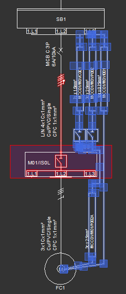
Below is an example of implementation of this feature. Motor circuit is created by inserting a final circuit to SB1. Then, auxiliary circuits are created, i.e. MCC01/M01/C001 etc.. Once these are added, each item is assigned to their respective equipment types and descriptions are also included. The rest including rectangles and lines are all hand drawn.