Top toolbar
Top toolbar consists of:
- Undo/Redo: These will reverse the action of an earlier action/restores an action previously undone.
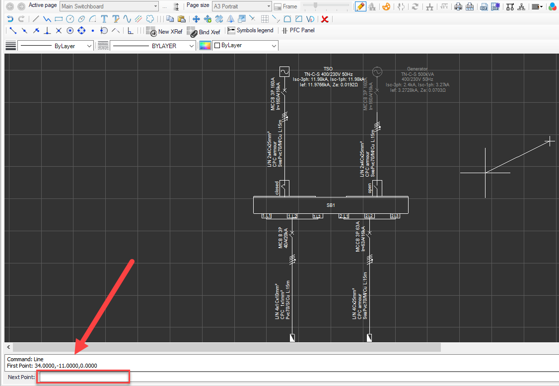
- Draw line: This will let the user to draw a line. First left click will mark the start point of the line where a second left click will mark the end point. This action is continuous and ElectricalOM will continue drawing lines connected to the previously drawn line. Right click or Esc key will stop the drawing action. Points can also be defined by using the command line below the drawing area. The point format is set as X,Y,Z coordinates separated by a comma where Z coordinates will be ignored within the Schematic module.
After the first line is drawn, Undo option, and after the second line is drawn, Close option will be available to the user. Typing Undo will cause the cursor to move to the previous point without drawing a line. Close command will tell ElectricalOM to close the shape by drawing a line between the first point and the last point.
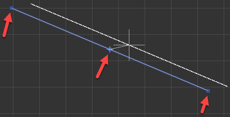
When a line is selected catch points will be displayed, as blue squares, which the user may click on them and modify the line. End points will deform the line where the mid catch point will move the line with the mouse cursor. The catch points are also available for every item.
- Draw polyline: This option is used to draw a polyline. Drawing a polyline is similar to drawing lines but the final shape will be considered as a single item by ElectricalOM unlike lines drawn one after the other where each line will be considered as individual items.
- Draw rectangle: This option is used to draw a rectangle. Start and end points can also be defined by typing in the coordinates into the Command area.
- Draw circle: A circle can be drawn by three ways. Centre point, 2 point, and 3 point. Centre point is the default option and it requires the user to select a point or type in a coordinate to represent the centre point of the circle, and then, defining the radius by typing the required value in to command bar, or clicking to a point with left mouse button within the drawing area. 2 point and 3 point options are simply the idea of specifying 2 or 3 points of a circle.
- Draw ellipse. This option is used to draw an ellipse. The first point will decide the centre point of the ellipse. The second point will represent the co-vertex of the ellipse. Then, the user must either click on the point which will represent the major axis distance or simply type in the value to the command bar.
- Draw arc: Drawing an arc can be done in three ways, centre point, and two types of 3 point. Centre point option requires a centre point, a radius, and a start angle to be specified, then, the cursor will draw a circle from the selected start angle. 3 point option has two versions, 3p and E3p. Both of the options requires the user to specify two points which represent
- Add text: will add a text to the schematics without using a text editor. Once this button is clicked, user must specify an insertion point and then a text height. Once these two parameter is specified, then the user can type in desired text. Right mouse button will end the session.
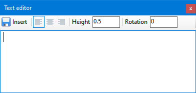
- Add text via Text editor: will display the Text editor window where the user can type in. Once desired text is formatted, then insert button must be clicked to close Text editor windows and return back to the drawing area where the user will specify the location of the text.
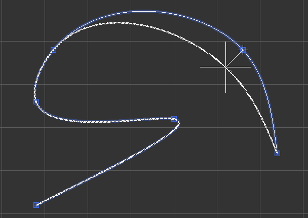
- Draw curved polyline (spline): This option is very similar to a polyline, but at the end it will smooth the lines to form a spline.
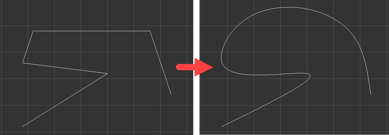
When selected, the catch points will be displayed (as squares), so, the user can modify the shape by dragging these points.
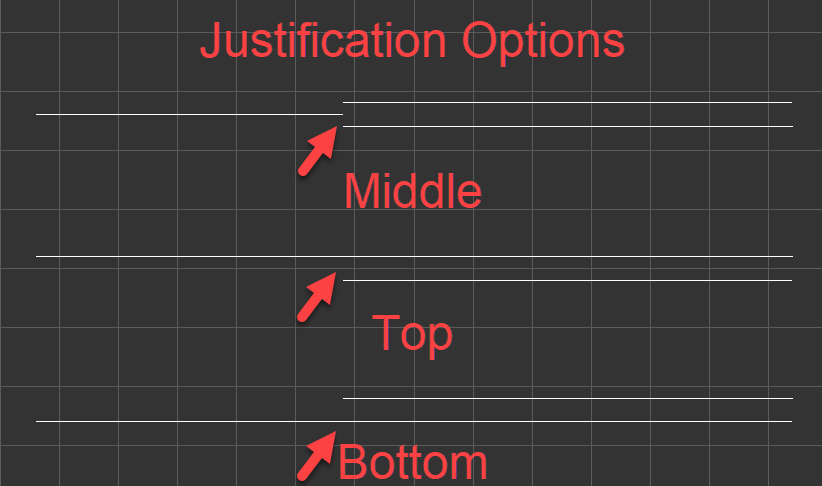
- Draw multiline: is very similar to a polyline but it draws two lines at the same time. There are three settings associated with multiline: Justification, Scale and Style. Justification indicates which line is taken as the reference. If this is set to Top then the top line is the reference, if Bottom is set then the bottom line is the reference, and if Middle is set then the reference is takes an the middle of the two lines.
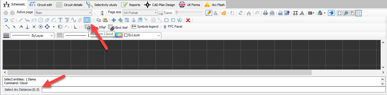
- Draw revision cloud: Revision cloud is simply selecting a start point and tracing an area the user wishes. The only parameter that can be set is the arc length and this must be specified before the first point is selected.
- Copy/Paste: These two options are very generic and they are used to copy and paste an object. The user must select an object before copying.
- Move: This will move the selected object to another location. The user must select an object before moving.
- Move Copy: This is similar to copying and pasting an object with a single click. The user must select an object before using this command.
- Rotate: Rotate option is used to rotate an object or group of objects. Objects can be selected prior to clicking on Rotate button or after the first click on Rotate button. If no object is selected prior to the first click, after the first click required objects must be selected following either pressing the right mouse button or Enter key on the keyboard to initiate rotate action.
- Mirror: Mirror option will create a mirror image of selected objects. Similar to rotate, object can be selected before or after the Mirror button click.
- Scale: Scale option will scale the selected objects according to a value either typed in to the command bar or with mouse clicks. A scale value can be entered after the selection of object directly to the command bar.
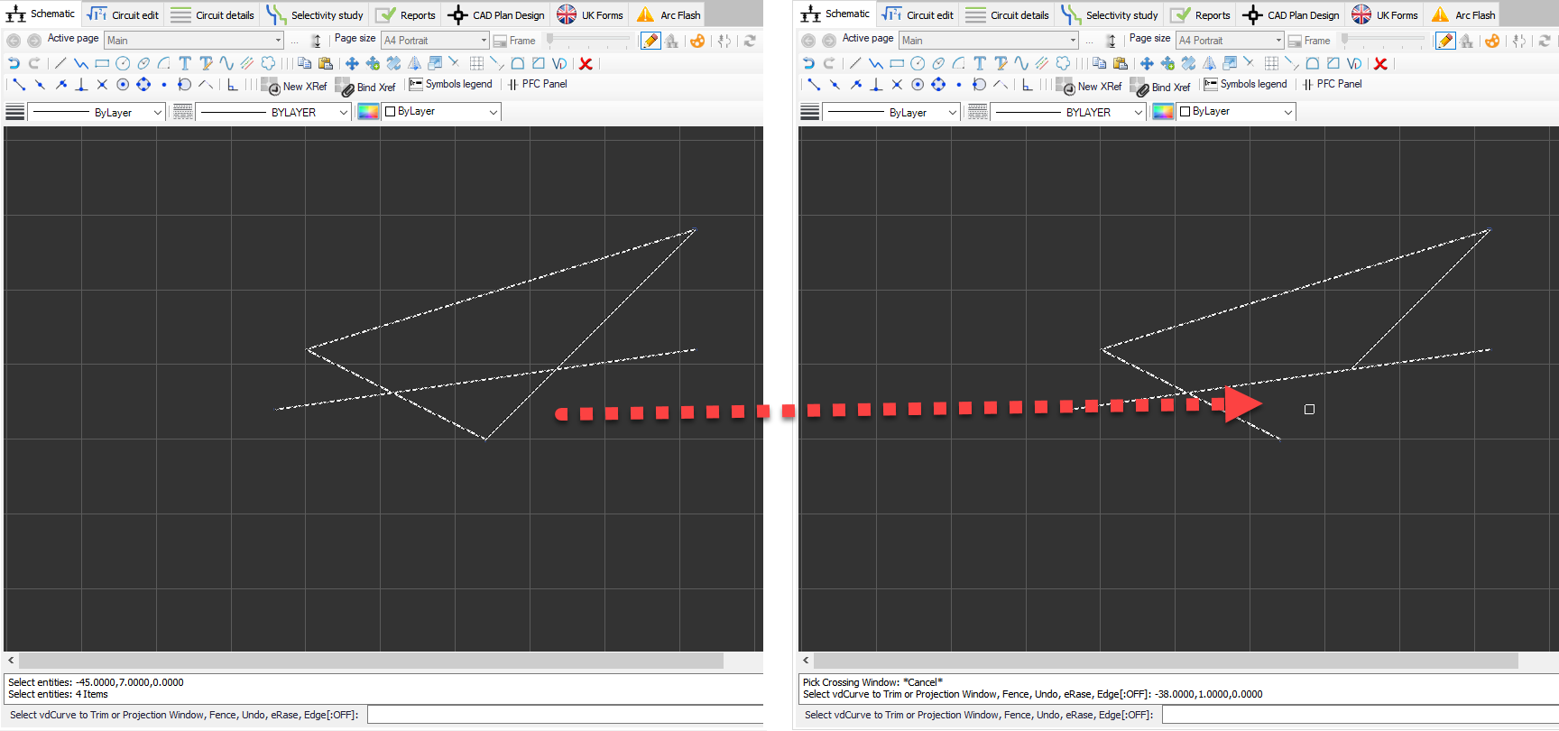
- Trim: Trim will remove the objects which meet the edges of other objects. In order to trim an object, two ways can be followed.
First, the user selects all the objects and then clicks Trim button, then, selects the part which will required to be trimmed.
Second, the user clicks on Trim button, then, selects all the objects and clicks right mouse button, then, selects the part which will required to be trimmed.
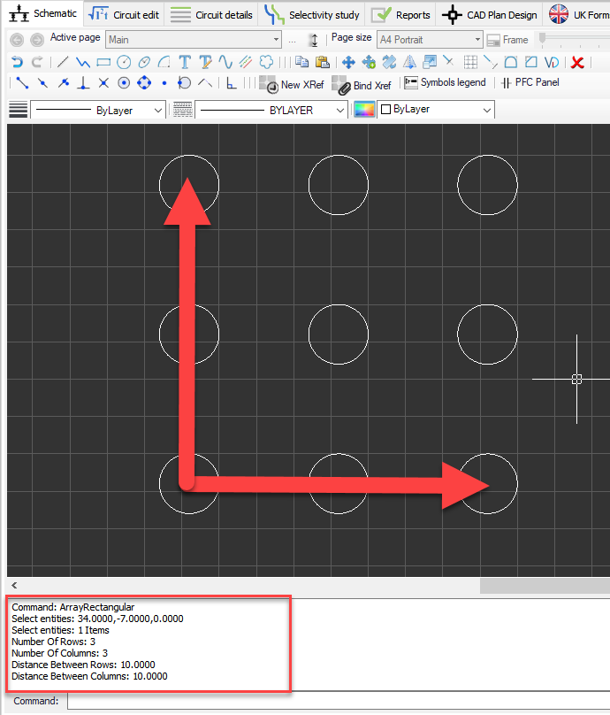
- Create array: This option will create a rectangular array of a selected object. Once the Create array button is clicked, then the procedure is as follows:
- Select entities
- Number of rows
- Number of columns
- Distance between rows
- Distance between columns
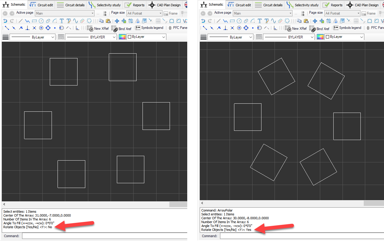
There is also a polar array option which is not available via the toolbar. It can be initiated by typing in ArrayPolar in to the Command Bar. This time the procedure is as follows:
- Select entities
- Centre of the array
- Number of the items in the array
- Angle to fill
- Rotate objects
Rotating the objects in polar array is shown below:
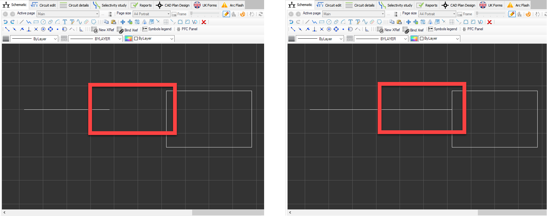
- Extend: This option is used to extend a part of an object to meet with another object. The procedure is similar to the Trim option.
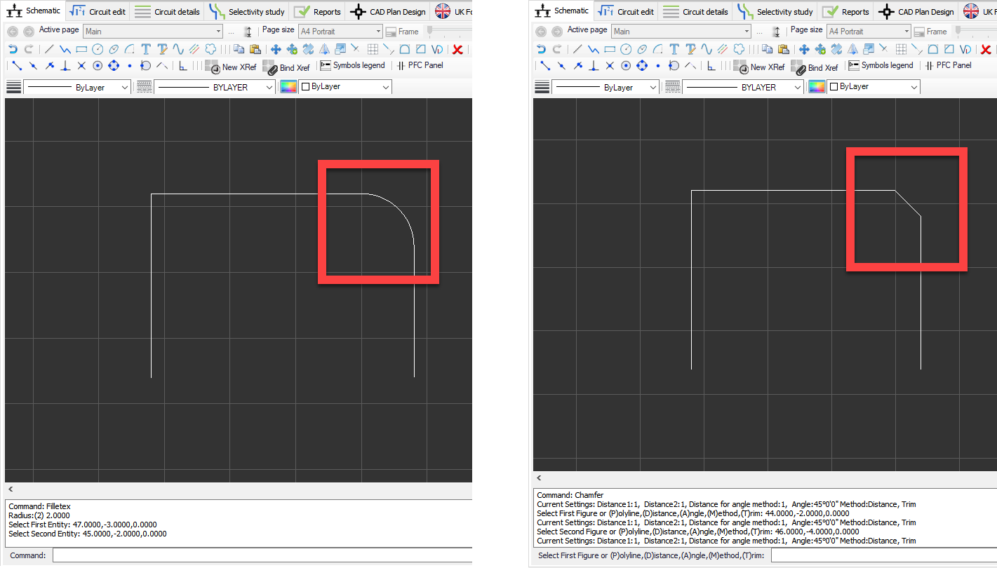
- Fillet/Chamfer: These two options are used to modify the corners. Fillet will round the corners where Chamfer will replace the corner with an angled edge.
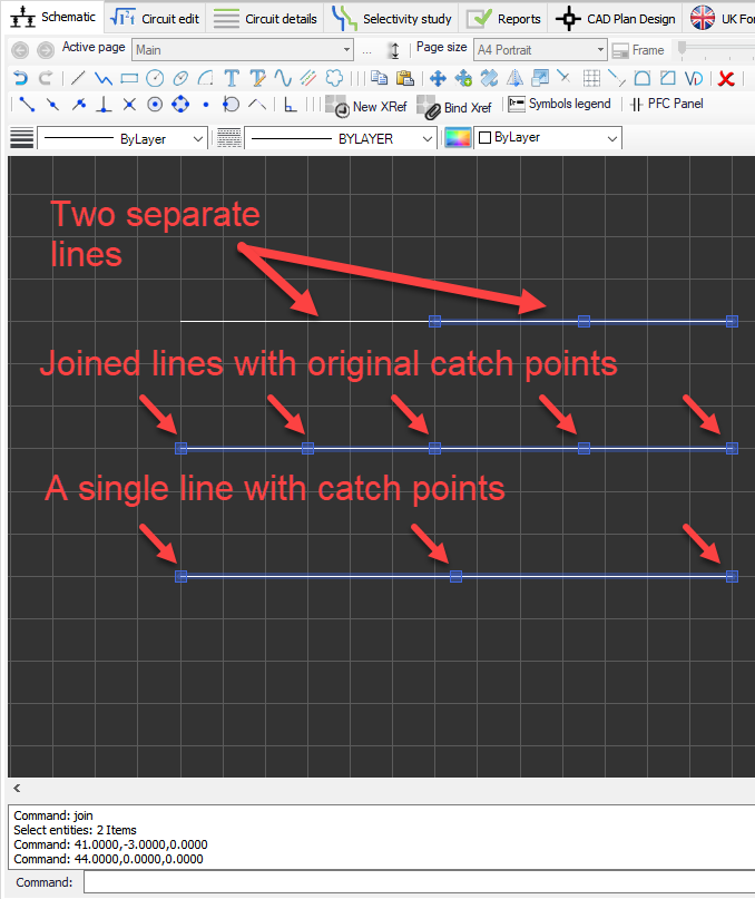
- Join: In order to join two lines touching each other, Join button is used. This will retain the catch points of original lines.
- Erase: Erase button will delete the selected object.