Earthing Tab
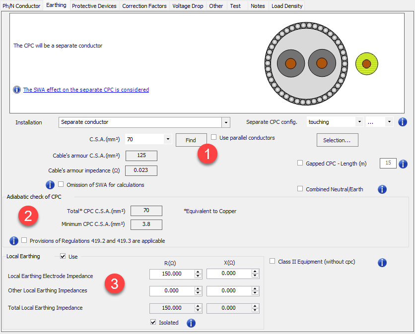
Earthing tab is used to set the protective conductor and earthing details for the selected circuit. The screen is divided into three main sections:
1- CPC settings,
2- Adiabatic check data, and
3- Local earthing settings which is available only for distribution nodes.
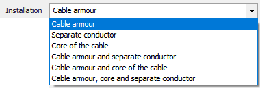
Depending on the feeder cable or conductor settings, CPC options will vary. For example, if the feeder is a cable type without an armour, then, using the cable armour as a CPC will not be an option. The CPC arrangement can be selected by using the Installation drop down list which is a dynamic list and contents will vary depending on the cable or conductor type selected by the user.
- CPC Settings
The CPC installation type can be selected using the Installation drop down menu. Installation options will vary depending on the selected cable or conductor. After selecting an installation option, ElectrcialOM will do various things depending on the selection.
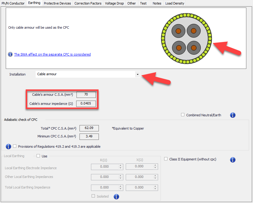
- Cable armour options will set the armour of the selected cable to be used as a CPC. In this case, ElectricalOM will calculate the copper equivalent cross section area and the impedance of the armour or sheath, and display it under the Installation drop down list.
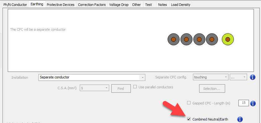
- Separate conductor option will create a separate conductor external to the cable or an extra cable to single cables, and use this as a CPC.
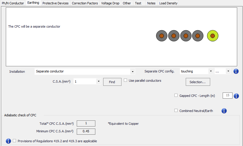
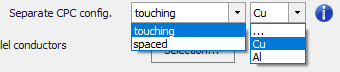
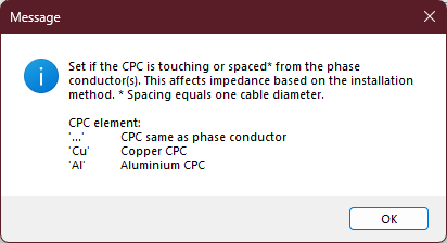
As long as the cpc consists of a separate conductor, cpc can be configured as touching or spaced which may influence the impedance of the cpc. Apart from this, the material of the cpc is made of can also be set by means of a drop down list.
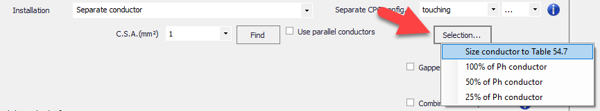
Size of the separate cpc can be adjusted using the cross-section drop down list manually or the Find button can be used. If Find button is used ElectricalOM will consider the adiabatic check, which is shown ar Adiabatic check of CPC section, and suggest minimum cross-section. However, Selection button can also be used to adjust the size of the cpc. Options are:
- Size conductors to Table 54.7, which will size the cpc according to BS7671 Table 54.7 taking the cross-section of phase conductor used.
- 100%, 50%, 25% of Ph conductor options will size the cpc according to the size of used phase conductor.
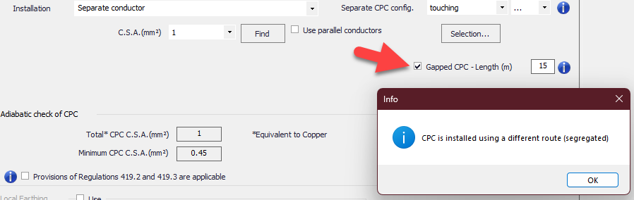
Another setting to fine tune a separate CPC configuration is the Gapped CPC option. This which tell ElectricalOM that the CPC has a separate routing . The length of this segregated route must be defined by using the text field.
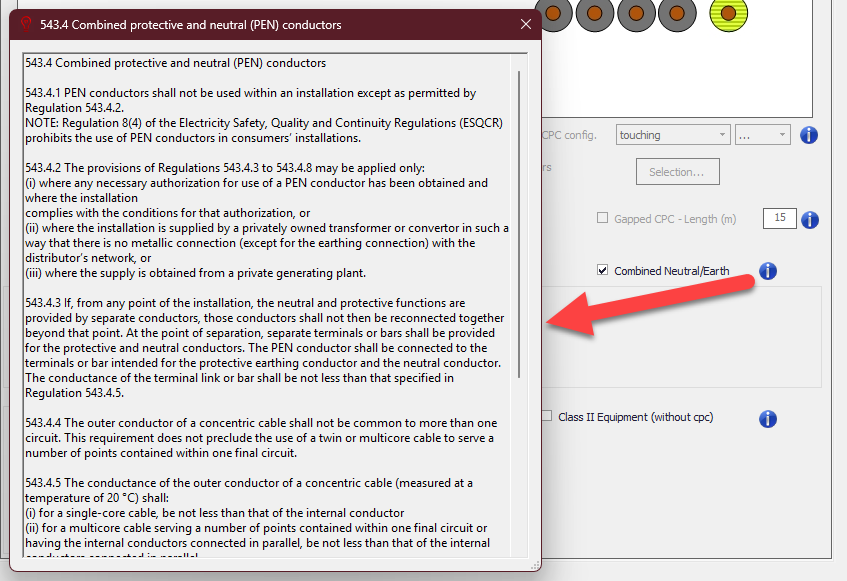
Another setting is the Combined Neutral/Earth tick box, which will combine the neutral and earth conductors. Before ticking this box it is important to read the information provided. Once this tick box is used, EOM will disable all other settings related with cpc and set .Z2 to the same value as Z1.
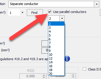
It is possible to use multiple parallel conductors for CPC. This option is initiated by ticking the Use parallel conductors check box and choosing the quantity by the help of the drop down list.
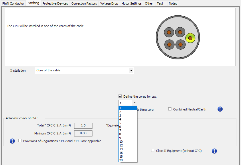
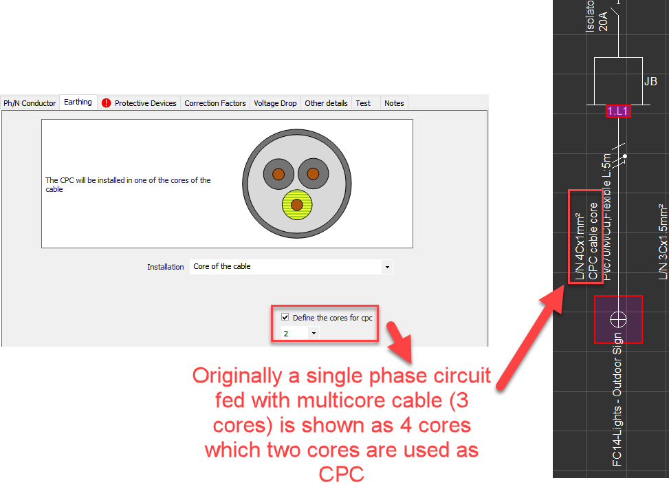
- Core of the cable option will add a new core to the selected multicore cable to be used as a CPC. The cross section setting will not be available with this option, however, the number of cores associated with CPC can be set by ticking the Define the cores for CPC box and selecting a number from the drop down list. Selecting multiple cores for CPC will also increase the core number of the cable and this will be indicated on the schematics.
Without earthing core option will remove CPC completely.
Combined Neutral/earth option is available for this CPC option too.
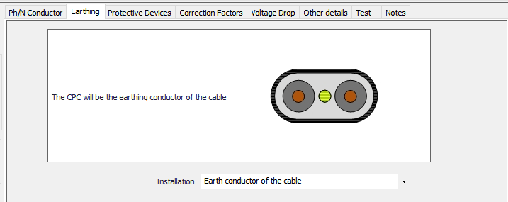
- Earth conductor of the cable option will be available with cables which already have an associated earth conductor, like twin flat cables. There will be no settings available for this option and ElectricalOM will set the CPC cross sections as shown below:
|
ElectricalOM's cross-section area settings for earth conductor of a Flat twin 70C PVC with CPC cable |
|
|
Line conductor cross-section area |
Earth conductor cross-section area |
|
1mm2 |
1mm2 |
|
2.5mm2 |
1.5mm2 |
|
4mm2 |
1.5mm2 |
|
6mm2 |
2.5mm2 |
|
10mm2 |
4mm2 |
|
16mm2 |
6mm2 |
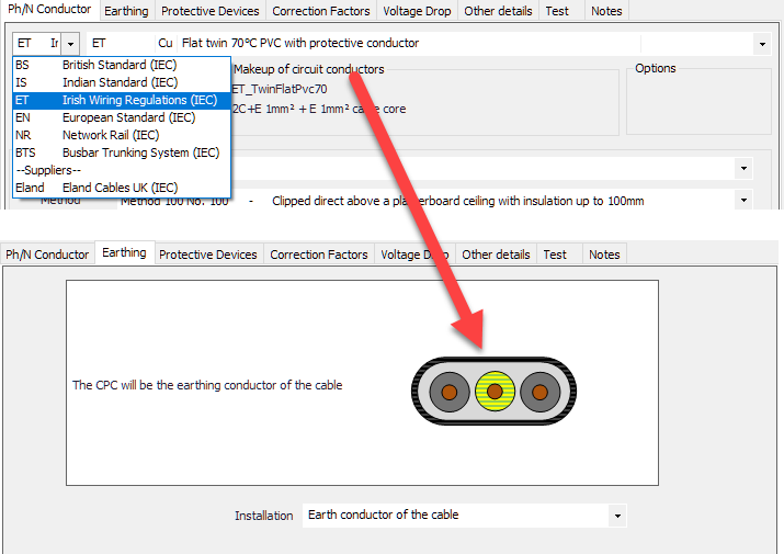
However, if the user selects a flat twin cable to Irish Wiring Regulations, then the CPC will be set to the same cross-section as the live conductors.
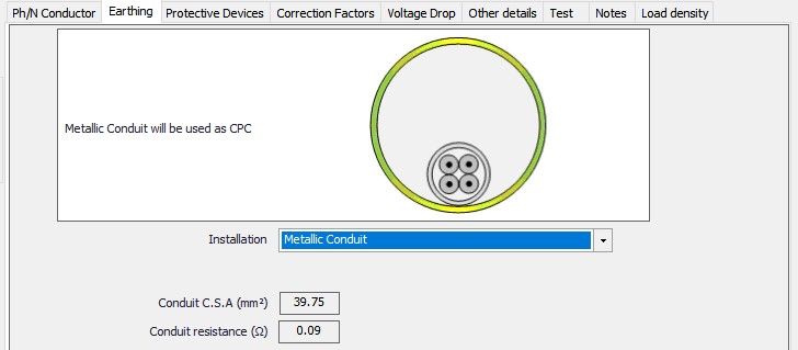
- Metallic Conduit option will be available only when a cable or conductor is run within a metallic conduit (See Ph/N Conductor Tab). ElectrcialOM will calculate the copper cross section area equivalent, and the resistance of the metallic conduit and display it under the Installation drop down menu
- Other CPC arrangement options include:
- Cable armour and separate conductor
- Cable armour and core of the cable
- Cable armour, core, separate conductor
- Core of the cable and separate conductor
- Earth conductor and separate conductor
- Metallic conduit and separate conductor
- Adiabatic check data
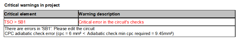
This section does not include any settings but is purely informative where the calculated minimum CPC cross section area and the actual cross section area of the selected circuit is shown and compared. ElectricalOM will calculate the required minimum CPC cross section area, and will display the result next to the Minimum CPC C.S.A (mm2). ElectricalOM will also consider all the components set as CPC by the user, and calculate a total cross section area and display it in the box next to the Total CPC C.S.A. (mm2). Any issues will be indicated by a red marker.

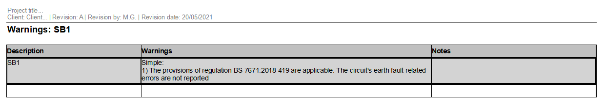
In the case of regulations 419.2, and 419.3, the user must tick the box next to Provisions of Regulations 419.2 and 419.3 area applicable so ElectrcialOM will not classify the warning associated with the CPC of the selected circuit as Critical but reduce it to Simple, however, the warning will still be visible on the Warnings page of a report.
- Local Earthing Settings
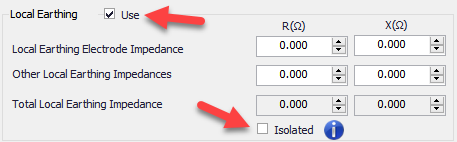
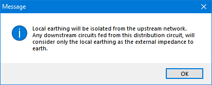
Sometimes, especially in TT systems, a distribution node may be earthed locally and further more, it can be isolated from the feeder side. ElectricalOM's Local Earthing tick box is designed to model this occasions. Once ticked, the resistance and reactance settings becomes available, so, the user can type in the values in to calculate the impedance at the point of local earthing. If the distribution node is not isolated from the feeder side then this value will be considered together with the rest of the system during the calculations, however, if the Isolated box is ticked, ElectricalOM will consider only the local earthing value for the rest of the system fed from this node ignoring the feeder side value.
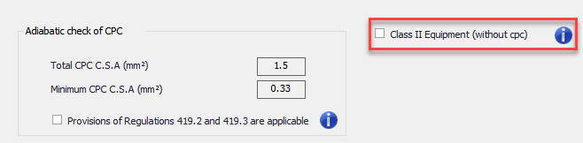
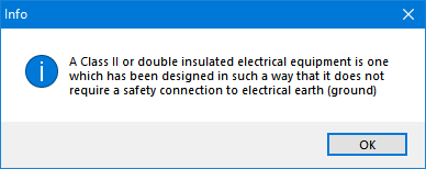
Local Earthing section also accommodates the setting for the Class II Equipment. When this box is ticked, Earthing settings will be completely removed.
Similar to Ph/N Conductor tab, Busbar Trunking System component also has a special Earthing tab, however, options below are only for Generic busbar trunking systems.
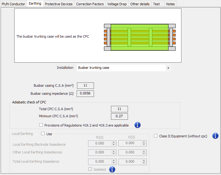
Installation drop-down list has three options:
- Busbar trunking case option will use the casing as the protective conductor.
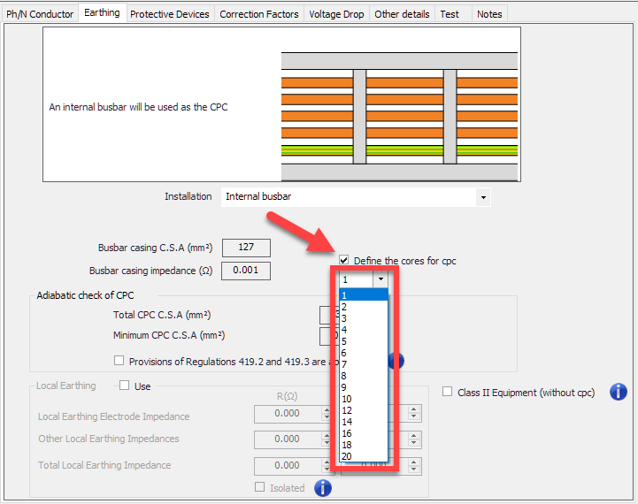
- Internal busbar option will use one of the busbars as the protective conductor. The user may choose the quantity of busbars will be used for earthing by ticking the Define cores for cpc tick box.
- Busbar trunking case and Internal busbar option will consider both options used at the same time. The user may choose the quantity of busbars will be used for earthing by ticking the Define cores for cpc tick box.