Ph/N Conductor Tab
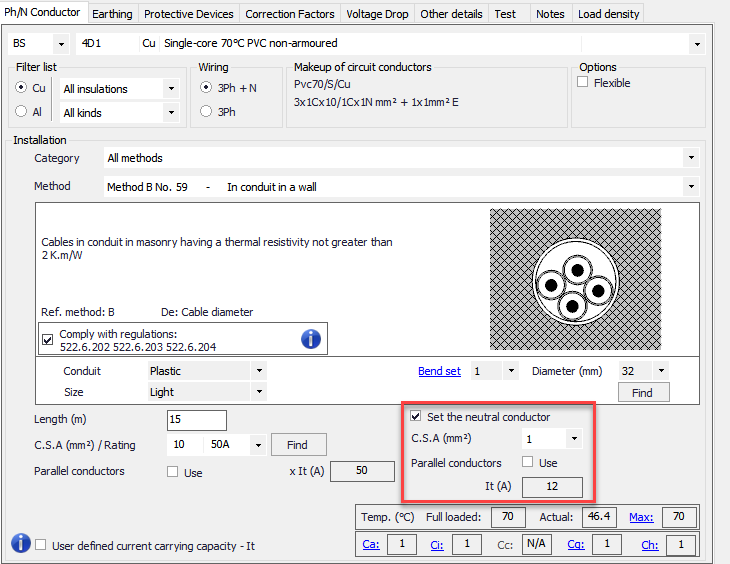
Ph/N Conductor tab accommodates data in regards to the phase and neutral conductors of the selected circuit. The user can select various options by using the drop-down menus and check boxes, and can type in the length of the conductors. A table, which shows some calculated data related with the cable or conductors, will be displayed at the bottom right corner of the Ph/N Conductor Tab screen.
At top level, the user can select which standard, or which manufacturer will be used for the selected circuit's conductors.
Next to the standard selection menu is the Conductor Type menu. The conductor types are dynamic and will change according to the standard or manufacturer selected but after this point we will focus on British Standard options. This list will have all the conductor types defined in BS7671 and the table reference no.s (e.g. 4D5) are also presented on the left hand side of the conductor list. On the right hand side ElectrcialOM also indicates any extra data about the conductor/cable like armour material, or sheath material. Selecting a conductor or cable type will assign it to the selected circuit as the feeder conductor or cable.
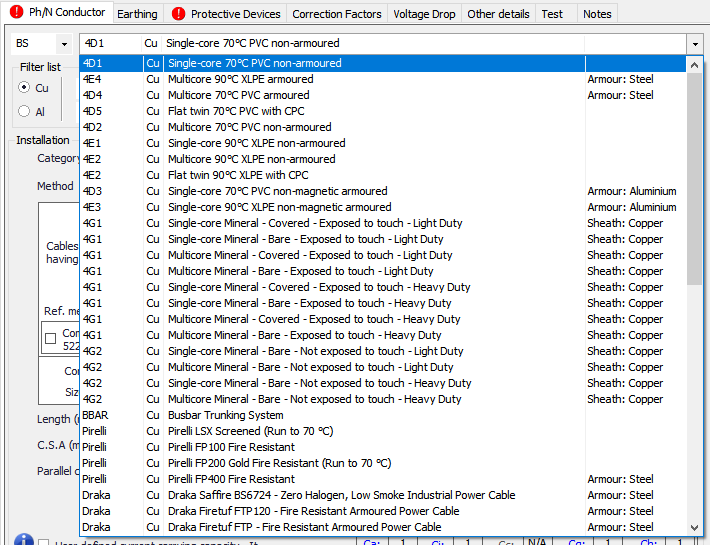
The list will change according to the filter applied. The conductor material filter is a selection between copper or aluminium where the user cannot see both at the same time, however, other filters are drop-down lists which include All option. Available insulation types are PVC, XLPE, and Mineral. Available cable variants are armoured, non-armoured, busbar, and flexible.
Depending on the selected option, ElectricalOM will show the structure of the selected conductor or cable under the title Makeup of circuit conductors.
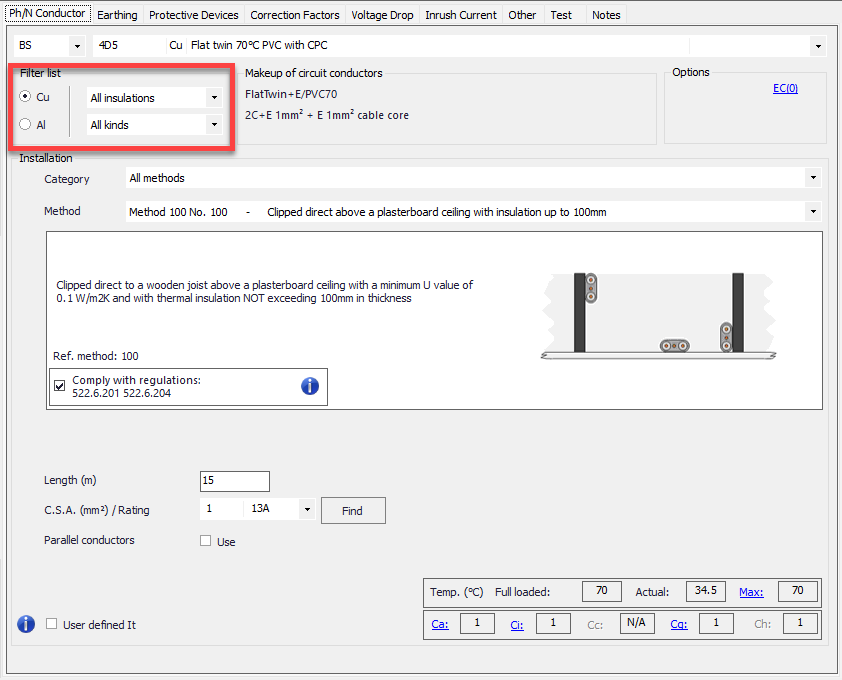
Extra cores can be added to a standard cable using the EC link. Once it is clicked, a windows will be displayed where number of extra cores can be selected via a drop down list. It is important to ensure compliance with the manufacture while adding extra cores. Also, it should be noted this extra core will not be contribution to any calculations or checks.
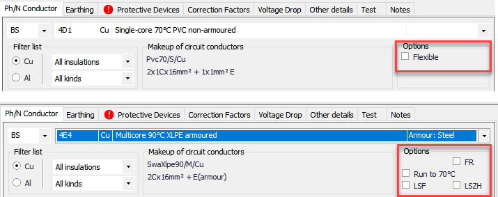
If there is an option in regards to the selected cable or conductor type, then, each of these options will be listed below the Options title as check boxes. The user may click on these check boxes to mark the option as applicable for the selected cable or conductor.
- Flexible: refers to stranded, continuous flexible cables/conductors.
- Run to 70°C: will set the max. running temperature of the selected cable to 70°C even if it can go higher by its specification.
- FR: refers to Fire Resistant
- LSF: refers to Low Smoke and Fume
- LSZH: refers to Low Smoke and Zero Halogen
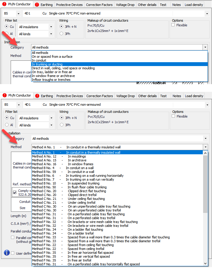
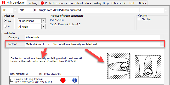
Middle section is reserved for the installation characteristics, e.g. category ,and method. ElectricalOM will only make the installation methods available for the selected cable or conductor according to BS7671. The category menu lists similar methods in groups and depending on the group the method menu lists the installation method in that group. If All methods option is selected at Category menu, then. all the methods available for the selected cable or conductor will be listed on the Methods menu list. ElectricalOM also lists the methods with their references according to BS7671.
Below the Method section, ElectricalOM will also describe the method in detail, and represent the installation method with a figure. Within the details area, there is also a tick box which will remind the designer to comply with regulations 522.6.201, 522.6.202, 522.6.203, and 522.6.204 of BS7671 if the installation method is subject to any of the aforementioned regulations. This tick box must be ticked to remove the warning form the Warnings Section.
If the selected installation method involves a conduit or a trunking, ElectricalOM will provide additional options below the tick box, where the user can define the material, and let ElectricalOM to find the required size for the conduit or trunking. This calculation will consider the number of bends (if conduit), and the cable properties (A Bend set represent a set of two 90 degree bends). The user must click on the Find button to calculate the conduit or trunking size when all settings are set..
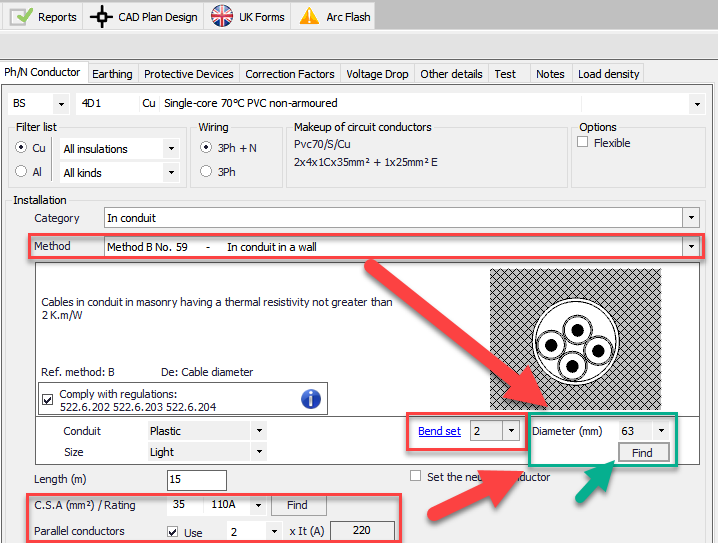
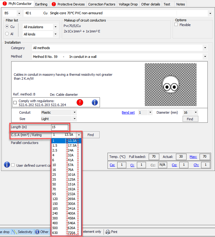
The last part of the Ph/N Conductor Tab is related with the physical details about the cable or conductor which includes the length, the cross section, etc. When a new circuit is inserted, the default conductors are set to 4D1, default installation method is set to Method B No.59, default length is set to 15 metres, and the default cross section is set to 1mm2.
The user can type in the length into the text field next to Length (m), ElectrcialOM will take the entered value as if it is in metres. Cross section area of the conductors can be selected using the drop down menu where the current carrying capacities are also shown next to the cross section area. All the current carrying capacity values are based on BS7671 and take the selected cable or conductor type, the installation method, and any other options ticked into consideration. Find button will let ElectricalOM to pick the possible lowest cross section area according to the defined values and options, but it must be noted that cross section area calculations are based on the protective device selected by the user (See Protective Devices Tab) and not on the load defined.
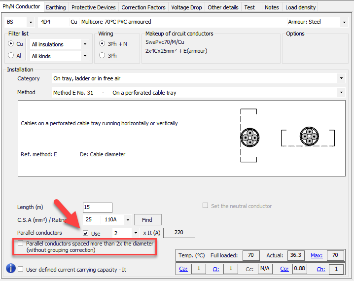
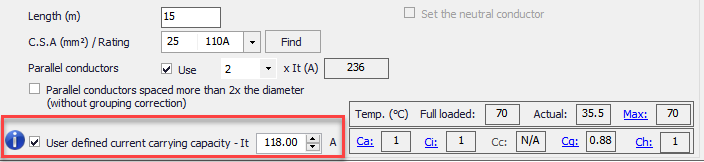
ElectricalOM also can work with parallel conductors as well. The user can tick the box next to Parallel conductors to enable parallel conductor options where the number of conductors can be selected from the drop-down menu. When using parallel conductors is in consideration, ElectricalOM will also modify the grouping correction factor according to the number of conductors selected by the user (See Correction Factors Tab). The total tabulated current carrying capacity is displayed next to the conductor quantity drop down list. If the conductors will be spaced to each other more than the twice of their diameters, then, the user must check the Parallel conductors spaced more than 2x the diameter (without grouping correction) option located below the Parallel conductors check box. Checking this box will set ElectricalOM, not to use the correction factor for grouping for this feeder.
ElectricalOM will also let the user to define a neutral conductor with different cross section area as long as the feeder is three phase, consists of single core cables and is not a final circuit. If all the prerequisites are met, then, ElectricalOM will enable the check box Set the neutral conductor, which lets the user to set the neutral conductor size different then the phase conductor. If this box is checked, new options will appear under the check box area which includes the drop down list to set the cross section area of the neutral conductor, check box to enable parallel cables option for neutral conductor, and the box which displays the tabulated current carrying capacity of the selected neutral conductor arrangement.
Sometimes defining a custom current carrying capacity other than the ElectricalOM values (which are basically BS7671 values) might be needed. In order to accommodate this, ElectricalOM has a check box at the bottom of Ph/N Conductor tab. When this check box is ticked, any value can be typed in to the text field, but this option must only be used if the manufacturer data is available as the entered value will override the BS7671 values.
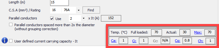
Lastly, a table which shows various data regards to the cable or conductor defined is located at the bottom right corner. It provides a quick review for the suitability of the defined cable or conductor. The data includes:
- The temperature of the cable at full load, at current load, and the maximum running temperature allowed.
- The correction factors associated with the cable or conductor.
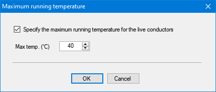
Clicking on Max link will launch the Maximum running temperature window where the user can define a maximum permissible temperature the selected cable can run. If the Specify the maximum running temperature for the live conductors tick box is not ticked then the max. temperature will be set to the default value for the selected cable or conductor type. If this box is ticked then the text filed below will be activated and the user will be able to type in a value to be used as the max. temperature,
Clicking on any of the the correction factors will activate the Correction Factors tab.
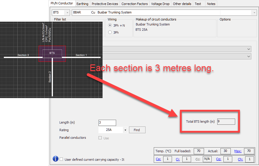
Ph/N Conductor tab is slightly different in case of a Busbar Trunking System. The conductor is set to BTS which cannot be altered, and installation section displays Manufacturer and Family drop-down lists which can be used to define the busbar trunking system used.
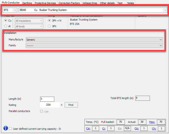
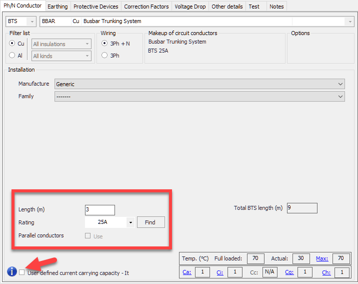
Bottom section is used used to define the length and the rating of the section. User also can define a manual current carrying capacity by ticking the User defined current carrying capacity - It tick box.
On the right hand side, ElectrcialOM will display the total BTS length. Total BTS length will display the total length of all the sections connected to the BTS box irrespective of their orientation, etc.