Protective Devices Tab
Protective Devices tab accommodates settings and options in regards to any protective device used in the selected circuit. It has two versions depending on the type of the selected circuit. If the selected circuit is a distribution circuit then there are two subordinate tabs available. These two subordinate tabs are Circuit protection, and Incomer disconnection/isolation, former being the outgoing part of the feeder mode which feeds the selected circuit, and the latter being the incoming part of the selected circuit. If the selected circuit is a final circuit, then, only the circuit protection settings are available.
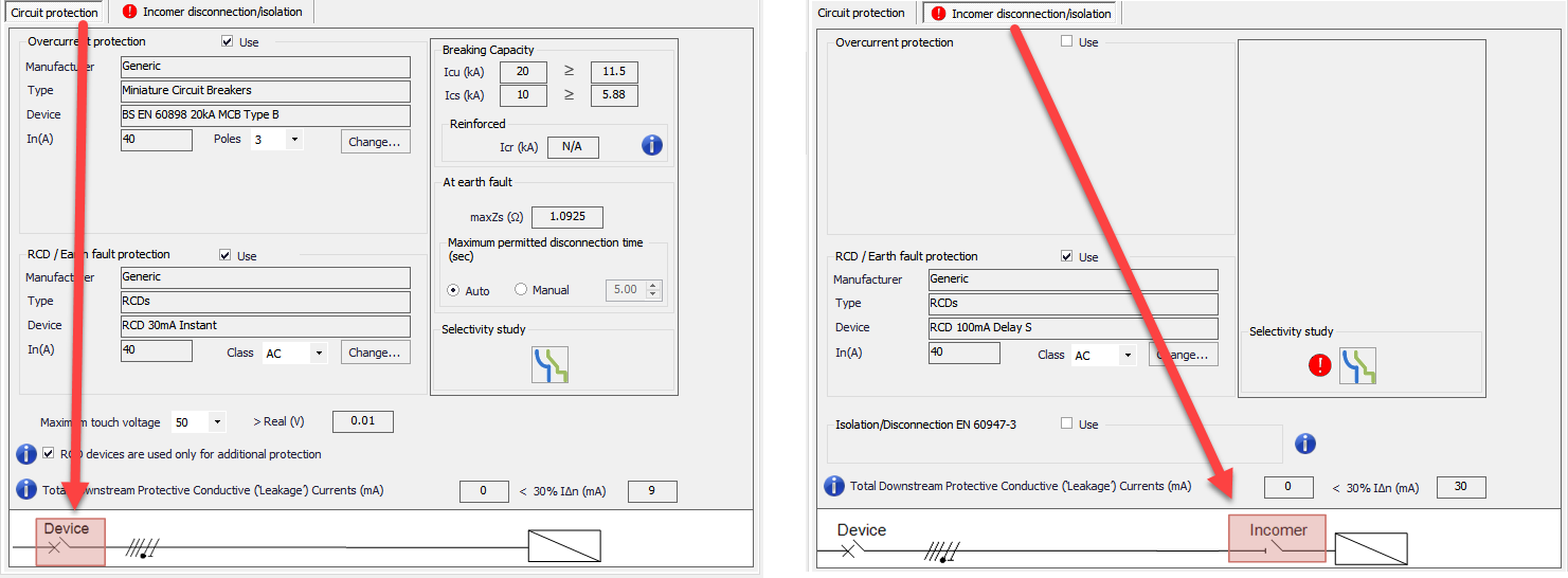
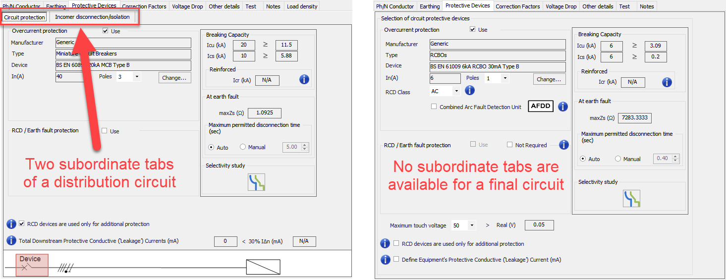
- Circuit protection
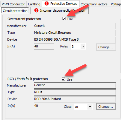
The user has two device options to use with the selected circuit, an overcurrent protection device and an earth fault protection device. The devices can be enabled by ticking the Use tick boxes next to the respective title. Once ticked, related option and setting fields will be displayed under the title, so the user can select and modify those.
Overcurrent Protection section has a drop down list for number of poles which will indicate if the neutral conductor will also be run through the protective device. If the circuit is a three phase circuit, the drop down list will have 3 and 4 as options, and if the circuit is a single phase circuit then the option will be 1 and 2. Change... button is used to modify the protective device as the user's preference.
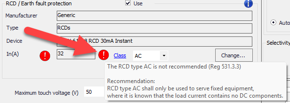
RCD/Earth Fault Protection section has also a drop down list but it is for the class of the protective device which are AC, A, B, F, B+.
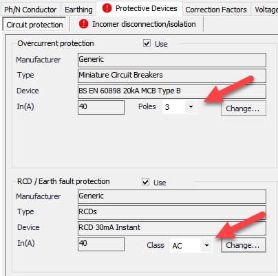
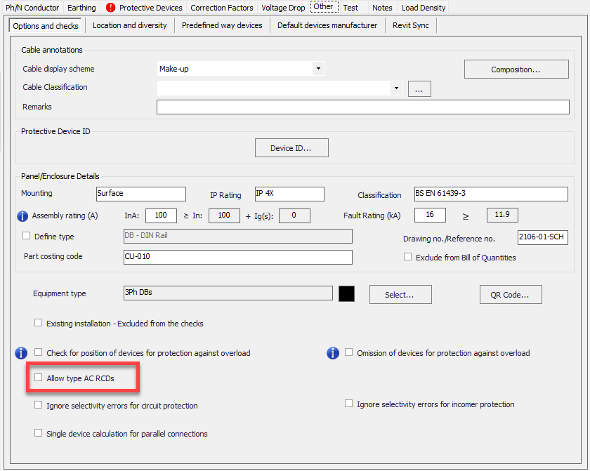
AC type RCD's will create a warning if it is not specifically allowed to be used from Other tab.
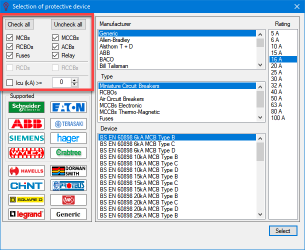
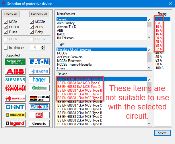
Change... buttons will initiate the Selection of protective device window which has various sections. Left top region is reserved for the filtering options which the user may select to see only the selected device types. If the device is a overcurrent protective device, the MCBs (miniature circuit breakers), MCCBs (moulded case circuit breakers), RCBOs (residual current circuit breakers with overload), ACBs (air circuit breakers), Fuses, and Relays options will be available, but if the device is an earth fault protective devise then RCDs (residual current devices), and RCCBs (residual current circuit breakers) options will be available. Underneath those, ultimate short circuit breaking capacity (ICU) filtering check box is placed which the user can define a value by typing in to the text field and refine the filtering further.
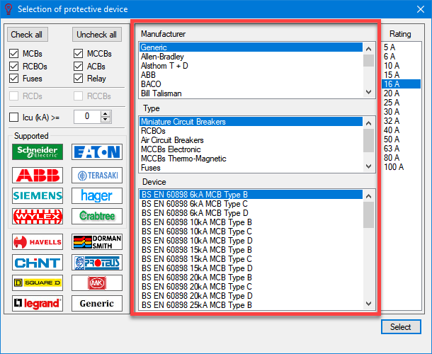
Middle section consists of three scrollable lists which are used select a manufacturer, a device type, and a device. If there is no manufacturer data, the user can use the generic data by selecting the Generic option from the manufacture list. The type and device lists will be updated accordingly depending the selected options. The device list will also consider the selected circuit data and marks the unsuitable items in red as a visual indication, however they are still selectable options.
Right hand side is for selecting the rating of the selected device type. The list is also updates itself depending on the selection and also the selected circuit data and unsuitable items will be highlighted in red, however they are still selectable options.
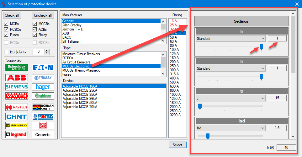
If the selected device has extra setting options due to its type such as an MCCB, then, an extra settings pane will be show on the right hand side of the Selection of protective device window. The variables can be set by using the sliders or by typing in a value to the related text fields.
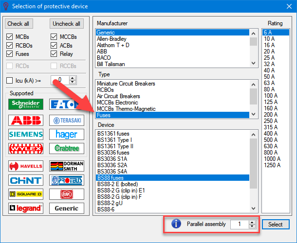
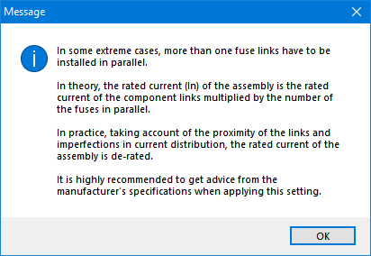
If the selected protective device is a fuse, then, ElectricalOM will let the user to use parallel fuses. Parallel assembly option can be enabled by ticking the tick box next to the Select button. The user needs t be careful before using such an arrangement and seek manufacturers' recommendations.
Right hand side of the Circuit protection tab is reserved for breaking capacity, earth fault data, and selectivity data of the selected circuit.
The Breaking Capacity section will display the comparisons of:
- ultimate short circuit breaking capacity versus maximum short circuit current at origin of the circuit, and
- service short circuit breaking capacity versus maximum short circuit current at the end of the circuit
for the selected device. Any warnings will be indicated by red markings.
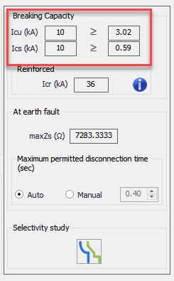
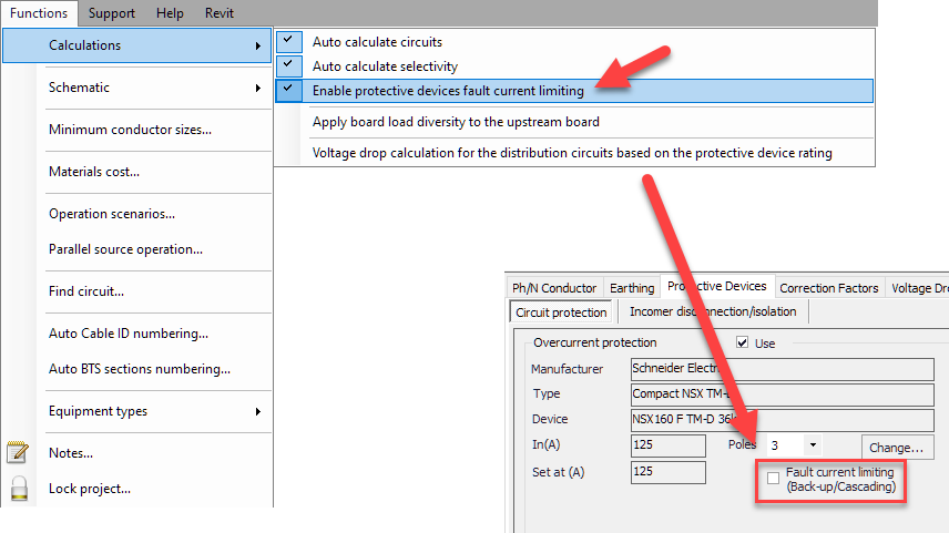
In many cases maximum short circuit current values under Breaking Capacity area are the same as the ones within the Calculations section, however, in some instances where the user enables the current limiting feature and selects a device from a manufacturer having current limiting feature, ElectricalOM will use the manufacturer's data to calculate fault current taking the limiting effect in consideration. This feature can be enabled from Functions menu. If Enable protective devices fault current limiting option is ticked, then another tick box will be displayed under Overcurrent protection section: Fault current limiting (Back-up/Cascading).
In cases Fault current limiting is enabled, the values within the Breaking Capacity section and the Calculations section will not be the same, the former being the fault current values taking into consideration the limiting effect, and the latter being the actual fault current values regardless of any device property or feature.
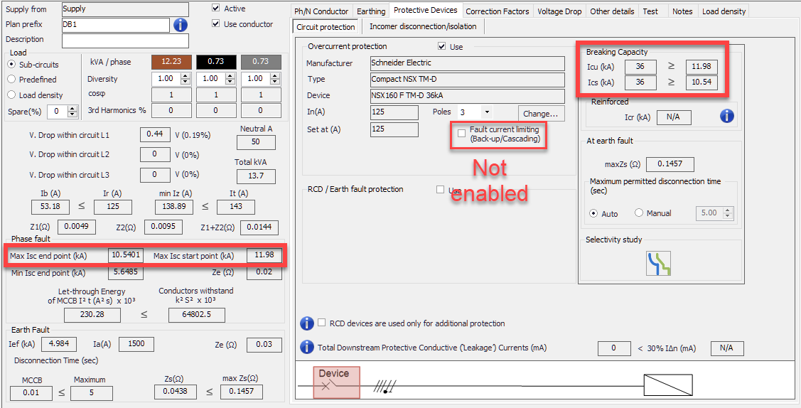
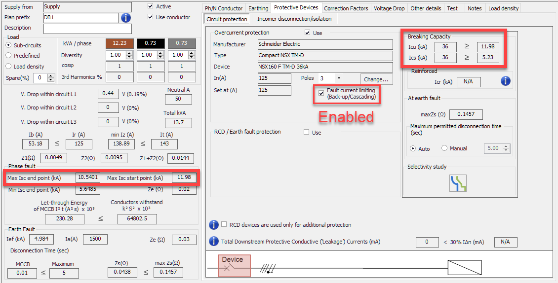
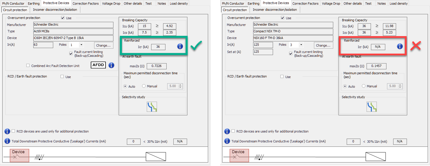
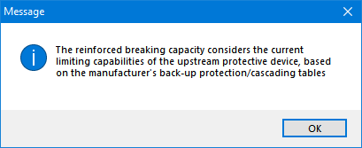
However ElectricalOM displays values for limited fault currents, it is not enough to achieve a current limiting assembly, and this option must be used with caution. A sub-section titled as Reinforced is also related with fault current limiting feature of protective devices and it is an indication fault current limiting effect is in fact achieved. ElectricalOM will display a reinforced breaking capacity value for a device only if the manufacturers' data is available. If no data is available for selected protective devices, the reinforced breaking capacity will be N/A and this means the limited fault current values are only tabulated and are not guaranteed by neither the manufacturer nor ElectrcialOM.
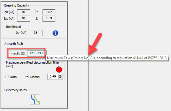
Next section named as At earth fault is used to display the calculated maximum earth fault loop impedance of the selected circuit by ElectrcialOM, take into account user defined variables (e.g. cable length, etc.) and regulation 411.4.4 of BS7671.
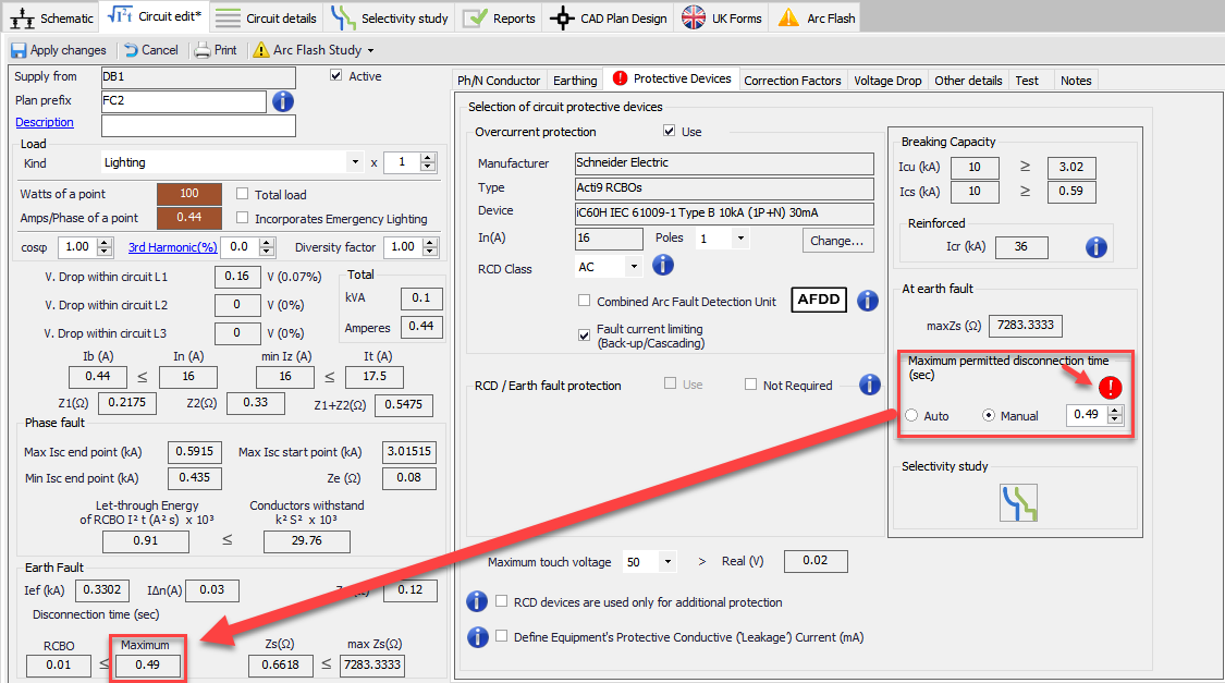
Underneath is the section where the user may select a value for disconnection time for selected circuit. If Auto is selected, ElectrialOM will assign the value which is defined in BS7671 for the selected circuit type automatically, where if Manual is selected, the text field will be enabled for the user to type in a manual value. If a manual value is entered, then, ElectricalOM will use this value as the disconnection time threshold for the selected circuit. In case of a higher value than BS7176 allows, then ElectrcialOM will warn the user with a red marking.
The next section, Selectivity study, accommodates a shortcut button for Selectivity Study Module tab. This section is used to indicate any issues with selectivity in case of an overcurrent or an earth fault. Red markings will appear if any issues detected by ElectricalOM. For details please refer to Selectivity Study Module Tab section.
Bottom part of the Protective Devices tab is reserved for maximum touch voltage setting, RCD usage setting, and leakage current setting.
- Maximum touch voltage setting will only be available if the selected circuit is a final circuit and a residual current device is used as a protective device upstream or with the selected circuit. There are two options to select from the drop down list; 25V or 50V. ElectricalOM will also show the actual touch voltage of the selected circuit in the text box next to > Real (V). It is also useful to know that this option will be unavailable if the distribution circuit is set to 24VAC, see Other details Tab.

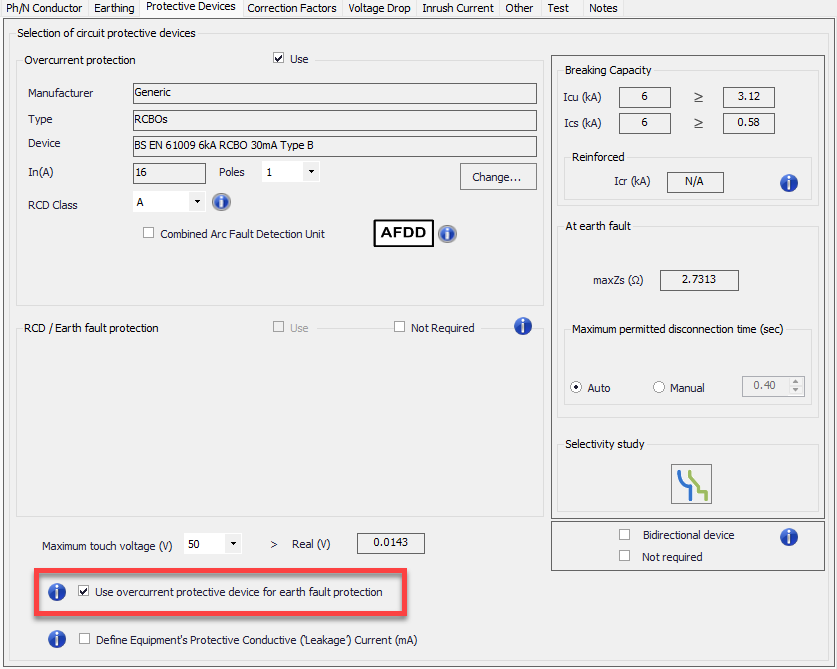
- Earth fault protection tick box is used to indicate whether the over current protective device or the RCD is used for earth fault protection which cause ElectricalOM to base calculations (e.g. max. Zs, max. disconnection time, etc.) correctly. It is also worth mentioning that this option will not be available if the designed system is a TT system.
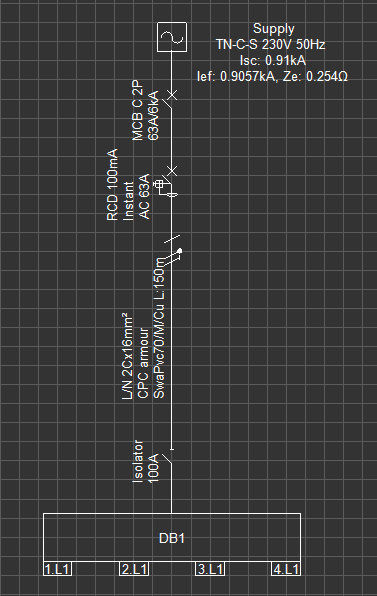
- The DB1 below is fed from a single phase source, and an MCB and an 100mA Instant RCD are places between the source and the DB1.
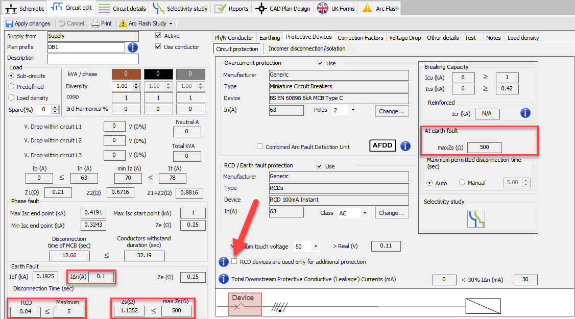
In first instance RCD is set as the primary protection against earth fault. ElectricalOM calculated the earth fault disconnection time taking the RCD into account and displayed RCD's response time in case of an earth fault because it would act faster than the MCB at that fault level.
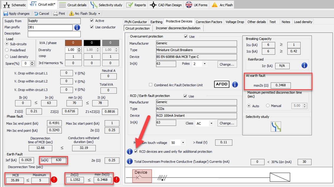
Where in the second case, the RCD is set as an additional protection. This time ElectrcialOM calculated and displayed the maxZs accordingly. Also, the disconnection time is based on the MCB's parameters. As the disconnection time fails with MCB, ElectricalOM flagged up relative warnings in the Warnings area.
In a case where the MCB is still faster than the RCD, even if the RCD is set to be as a primary protection device against earth fault, ElectricalOM will use the MCB parameters rather than tehRCD for disconnection time and related calculations.
Leakage current settings are is a dynamic one and will change according to the type of the circuit. If the circuit is a final circuit, the ElectrcialOM will have a tick box to let the user to enter a value for the leakage current for the selected circuit. The user can tick the box to enable the text field to type in a value. ElectrcialOM will provide some typical values when the user clicks on Typical values link, which are borrowed from BS EN 60355-1.
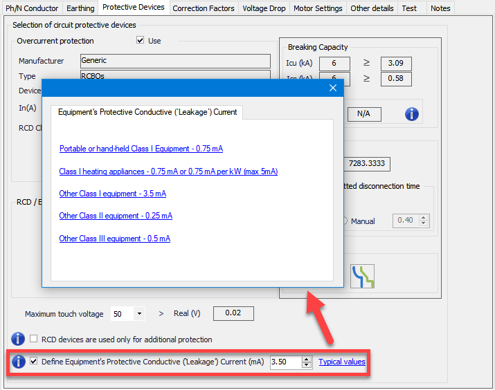
On the other hand, if the circuit is a distribution circuit. then, ElectrcialOM will just display total leakage current at the selected distribution node taking into account connected circuit data. If the total downstream leakage current is higher than the 30% of the RCD's IΔn then a red marking will indicate the issue.


- Incomer Disconnection/Isolation
This tab is very similar to Circuit Protection tab except an extra option of using an isolator is presented. The tick box must be ticked by the user in order to enable the usage of an isolator. ElectricalOM lets the user to define the type, and the rating of the isolator by selecting a type from a drop box list and typing in a rating in the text box.
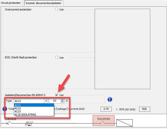
There is nothing automated in case of an isolator and the user needs to define the rating manually, however, if the rating is not suitable, ElectrcialOM will still indicate the issue and warn the user.
