Drawing a reference wire
Sometimes it is not possible to draw wiring with start and end points at the same time. For example, if we want to show the wiring of a light switch which operates a light on the upper floor, or we may want to show a feeder cable for another board which is located on a different layer. In these cases, Properties Tab can be used. We will see how this is achieved here, however, other features of the Properties tab will be discussed in Properties Tab section.
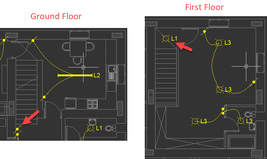
Let's assume we have a switch at the ground level which will operate the light on the first floor as shown below. We will also assume the wiring length from the switch to the light on the upper level is 8 metres.
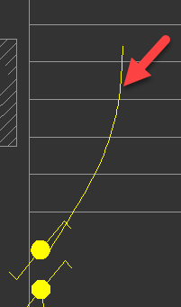
Now, using the Draw wiring button, we will draw a piece of wiring as shown below.
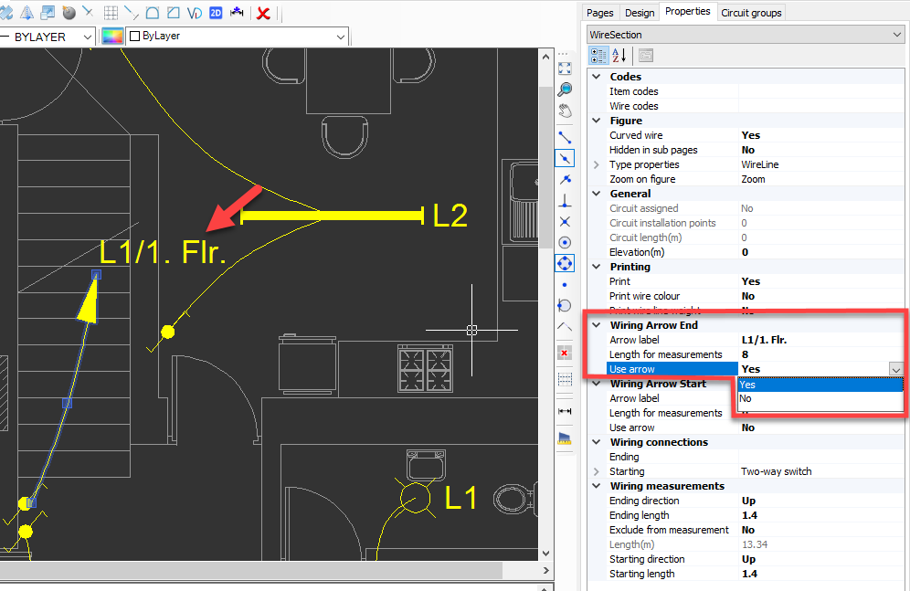
Then, we will navigate to the Properties tab, and define a label and a length for and end point arrow, see below.
Now, visually we managed to show the wiring from the switch. We can also do a similar thing for the lighting point to show the wiring to it as below. However, this time we will not define a length for this piece of wiring, because when we assign the wiring to a circuit we want this extra length to be added only once.
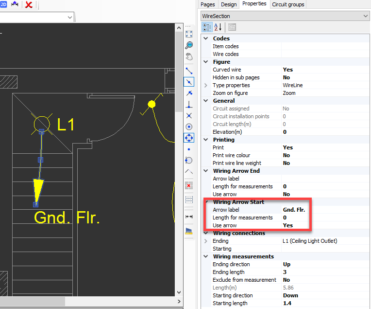
Once this pieces are assigned to a circuit, CAD Plan Design will add the specified length to the total length of the wiring which is 8 metres for this example, see below.
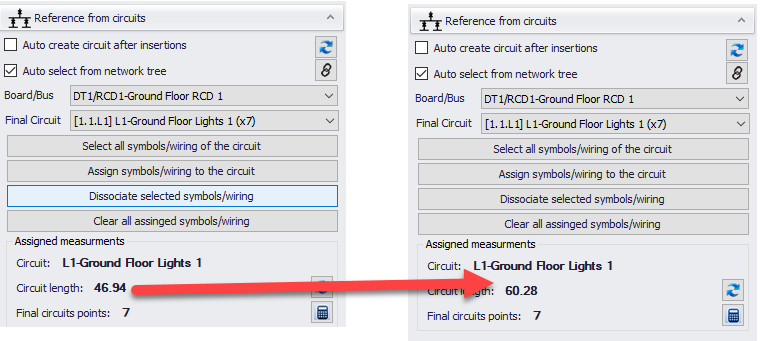
For further details about assigning symbols to circuits, please refer to Assign CAD Plan Design symbols to ElectricalOM circuits.