Wire by Selection
It is also possible to select symbols and let CAD Plan Design module to do the wiring automatically. When the user click on Wire by selection, Wiring properties screen will be displayed on the side panel, curved line option, and elevation can be set from here. When the cursor is within the drawing area it will look like a small square while selection is ongoing. Symbols can either be selected by drawing an imaginary rectangle which will highlight the area inside to see if the symbols are within the range, or by directly clicking on the symbols.
In the example below we placed symbols in numbered order, and selected them using the rectangle feature. Selection is done by clicking at the upper left corner following another click at the lower right corner. User may continue select more symbols.
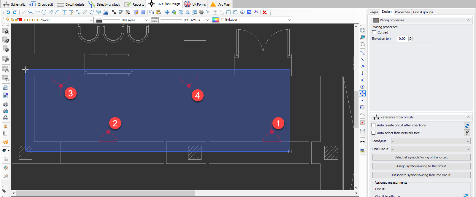
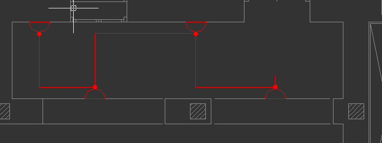
A right-click or an Enter key press will finalise selection and wire the symbols selected. As it can bee seen below, CAD Plan Design wired the symbols according to their insertion order.
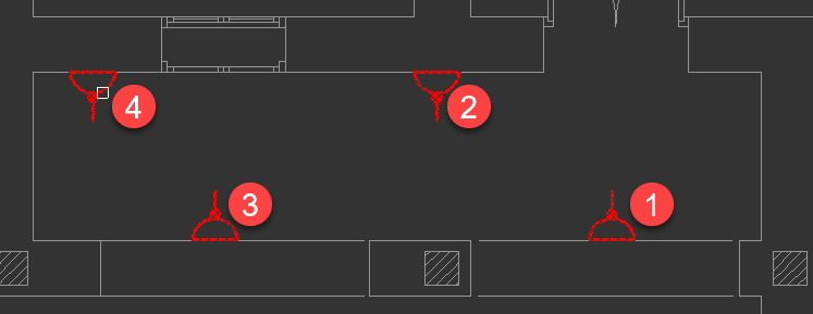
This time we will select the symbols directly by clicking on them. Selection is done in the order indicated below.
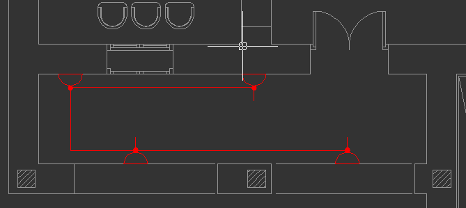
This time, CAD Plan Design considered the order of selection while wiring the symbols.