LV Protective device Tab

This tab accommodates tail conductor and supplier's protection parameters. They are not compulsory to use so they both have an associated Use tick box to enable or disable.
The user can define tails conductors by selecting a cable type, an installation method, and a cross-section area by using the associated drop-down lists. In case of a parallel arrangement, number of conductors can be set by using the up and down arrows next to Parallel text box. The length can be modified by typing in the required length into the Length text box in metres.
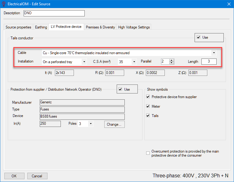
ElectricalOM will display the tabulated current carrying capacity and impedance parameters of the conductor below the settings.
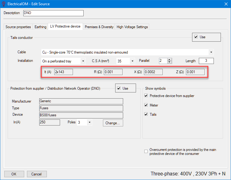
If the current carrying capacity of the selected conductor or defined arrangement of conductors is not appropriate, ElectricalOM will display a warning icon.

In order to define supplier's protection parameters, the user can click on Change button to select an appropriate protection device and use the Poles drop-down list to set the number of poles protection is used.
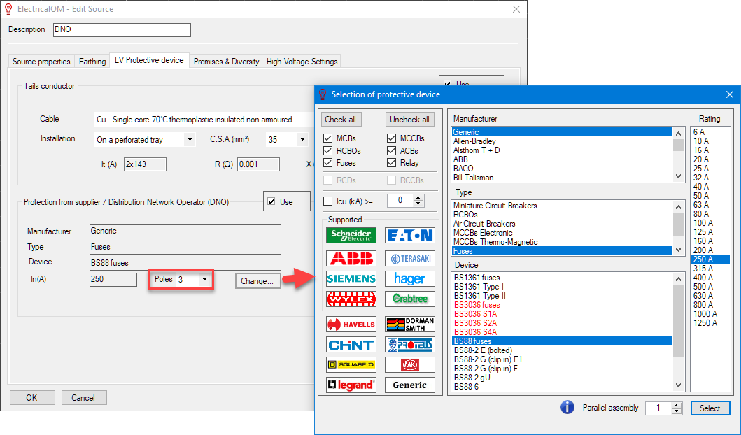
If the protection device rating is not appropriate ElectricalOM will display a warning icon.

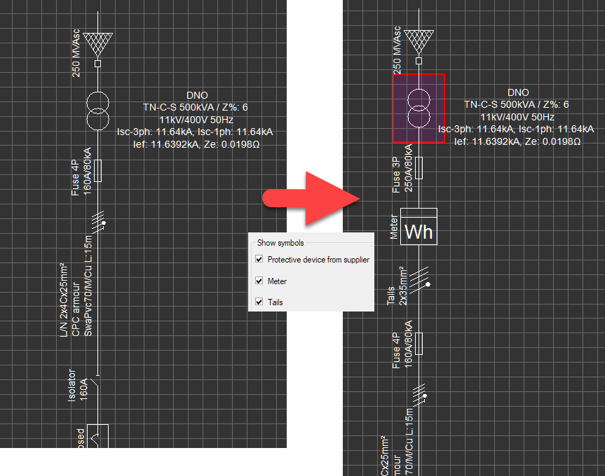
Show symbols section is used to set these components described above on the schematic. If the tick box is ticked then the related symbol will be displayed on the schematic.
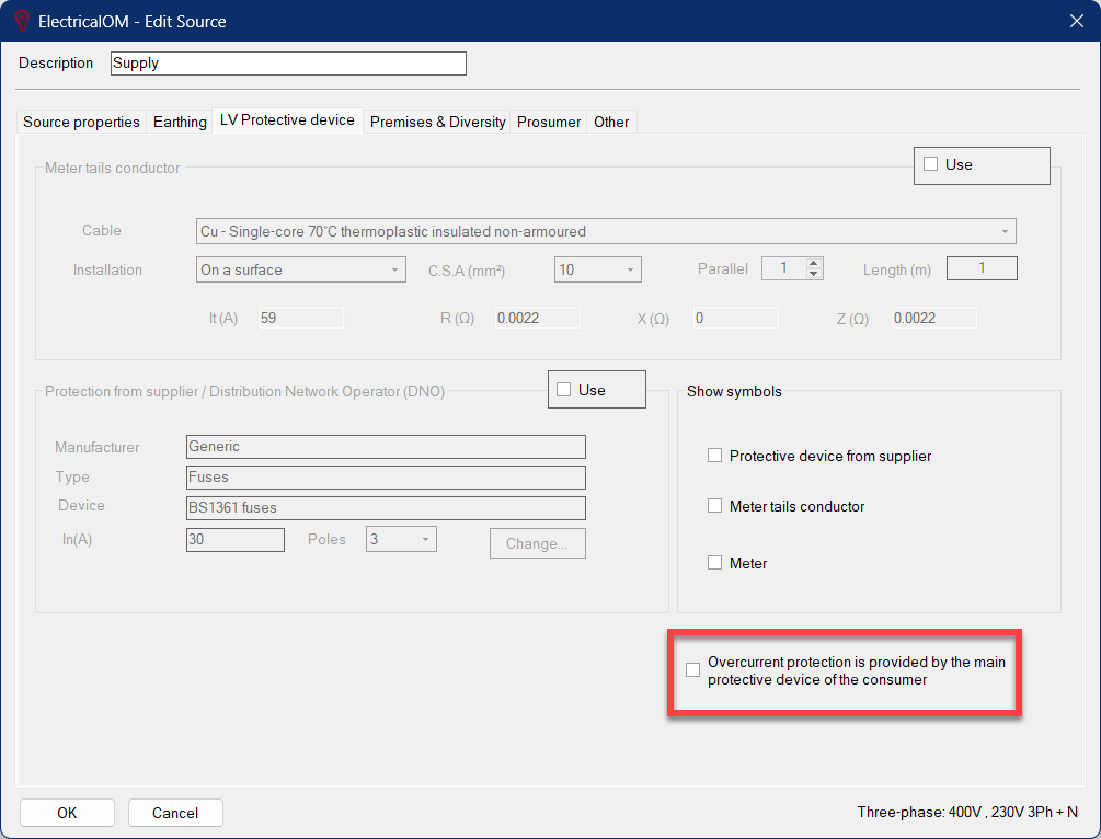
At the bottom right of the LV Protective device tab, a tick box is available to set ElectricalOM to consider incomer protective device instead of the supply protective device to base relevant calculations. This option is ticked if the Method of supply is set to Transformer by default.
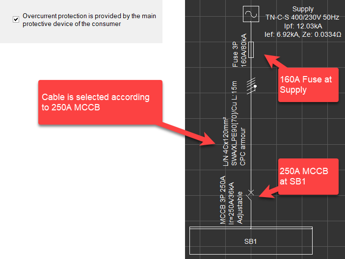
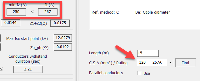
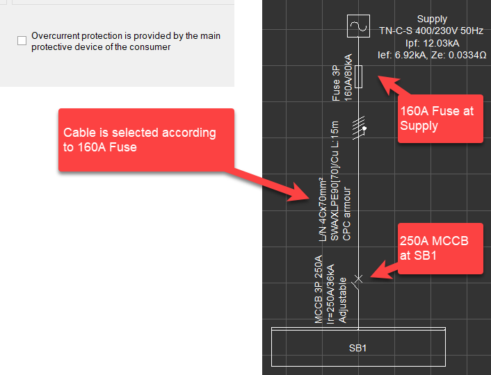
Just to make this clear, consider the case below which has a 160A fuse at supply and a 250A MCCB as an incomer to SB1.
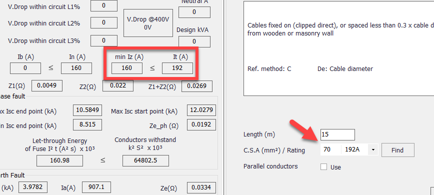
Now consider the case where the box is ticked.
