Distribution circuits single line diagram and layout

Distribution circuit single line diagram
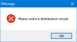
ElectricalOM can create an SLD which will show the circuits fed from the selected distribution circuits only. As Distribution circuit SLD is a distribution circuit based command, the user must select a distribution circuit before running this command. If any circuit other than a distribution circuit is selected, ElectricalOM will display a message window to warn the user that the selected circuit is not a distribution circuit.
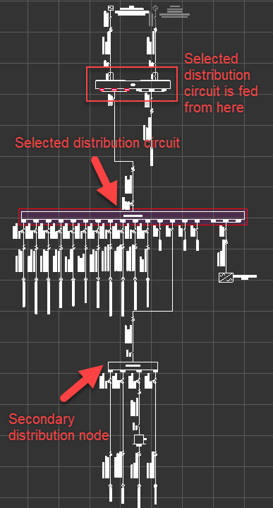
The SLD will be created based on the selected distribution circuit, which means the resulting SLD will have the origin being the distribution node which the selected distribution circuit is fed. Also, it is a single level command which means it will show a distribution node fed from the selected distribution circuit as a single load without any further details.
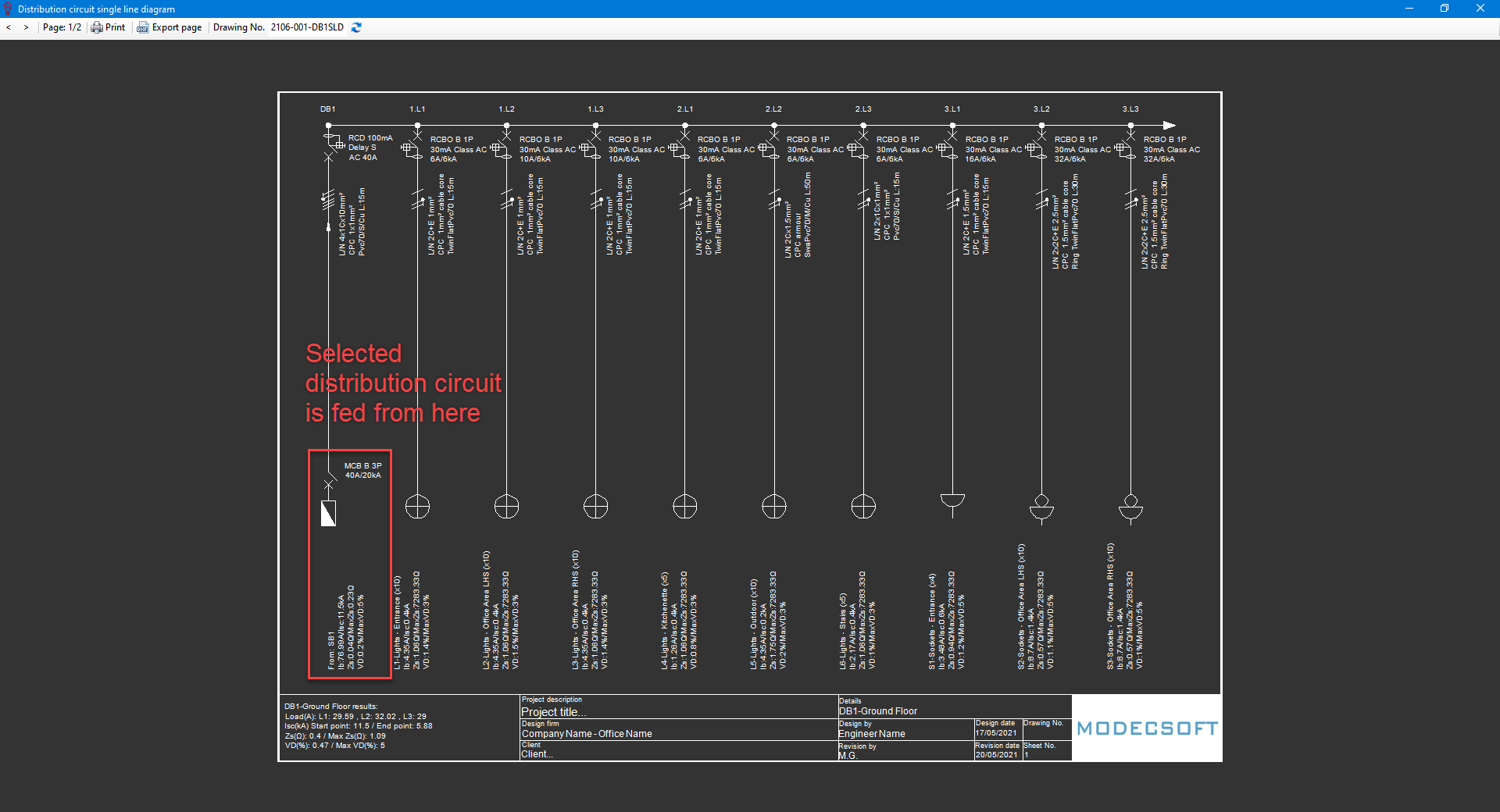
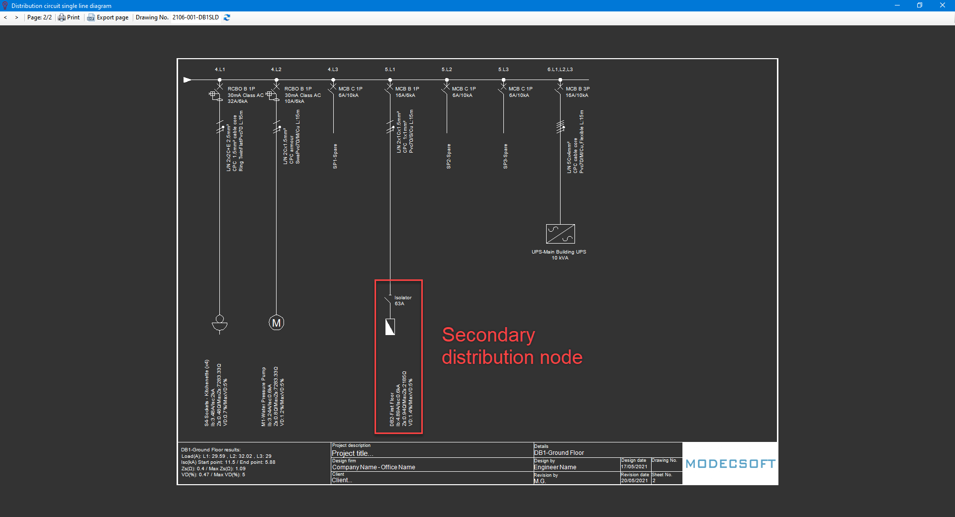
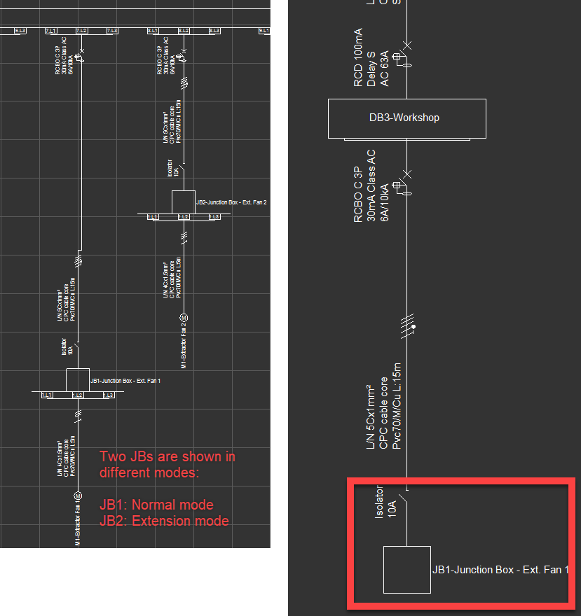
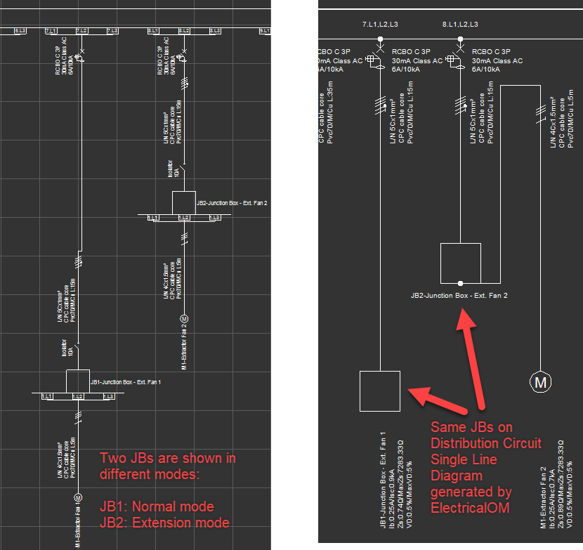
When Force extension mode is used for a node, then, this circuit will be shown on the same SLD as the selected distribution circuit, however, if normal mode is used to show a node then this node will be regarded as a secondary node and circuits fed from this node will not be shown.
The toolbar of Distribution circuit single line diagram has:
- Navigation buttons to navigate between pages of the generated SLD,
- Print button which acts the same as described under Print Page title above
- Export page button which is the same as described under the title of Export active page
- Drawing No. text field where the user can type in the desired drawing number which will appear on the title block. The rest of the data is generated from project properties and page descriptions.
- Refresh button to apply changes made to the drawing number by refreshing the title block.

Distribution circuits layout
ElectricalOM can also produce block cable diagrams, but, this is a system wide option and will generate the BCD for the whole system. The BCD will be displayed inside a print preview window where the user may choose to print or export the BCD.
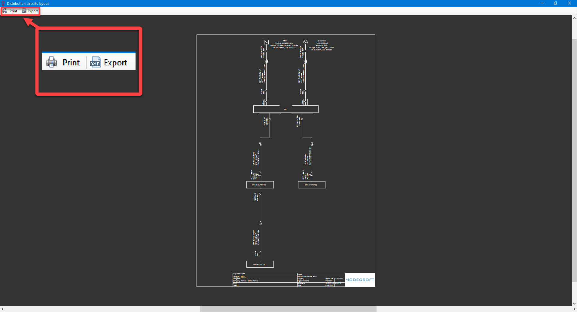
When Force extension mode is used for a node, then, this circuit will not be shown on the BCD, however, if normal mode is used for a node, then, it will be shown as a block on the BCD.
