Design defaults Tab
Design defaults Tab
- Phase prefix: Users can set their own abbreviations for phases using the fields marked as L1, L2, and L3. The phase fields are restricted with two characters. The refresh button will apply the setting to existing components.
- Main supply orientation: There are four options available to select; Up, Down,Left , and Right.
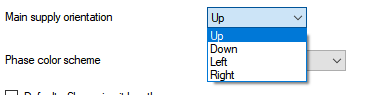
This will change the default orientation of the schematics as shown below:
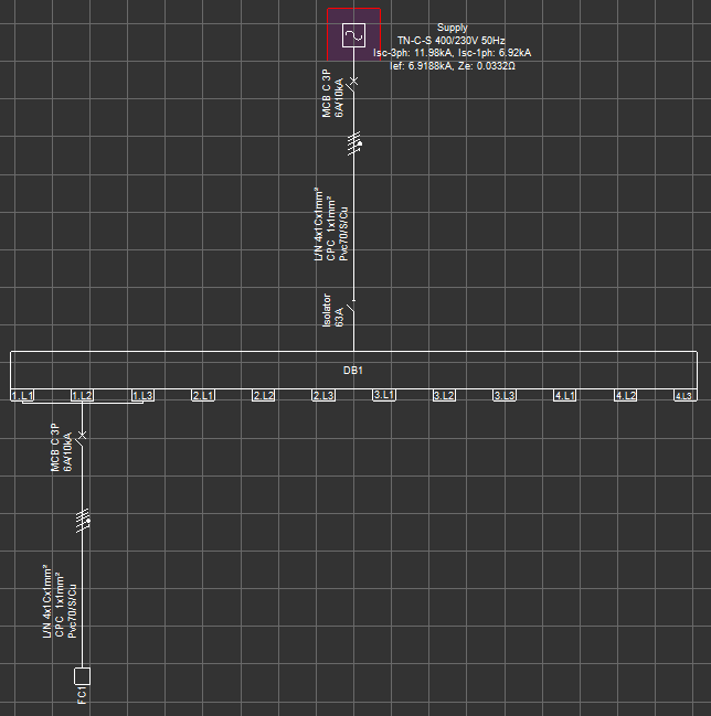
- Main supply orientation - Up:
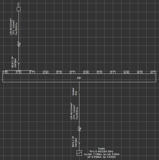
- Main supply orientation - Down:
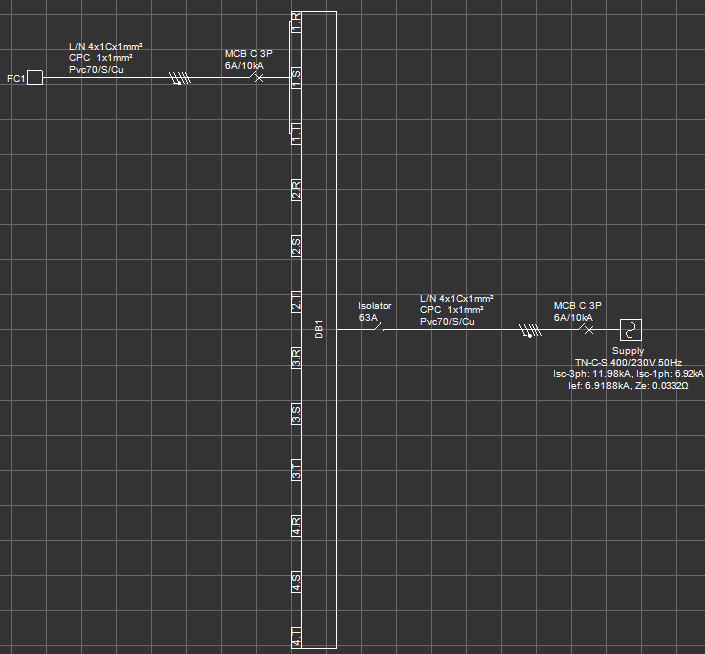
- Main supply orientation - Left:
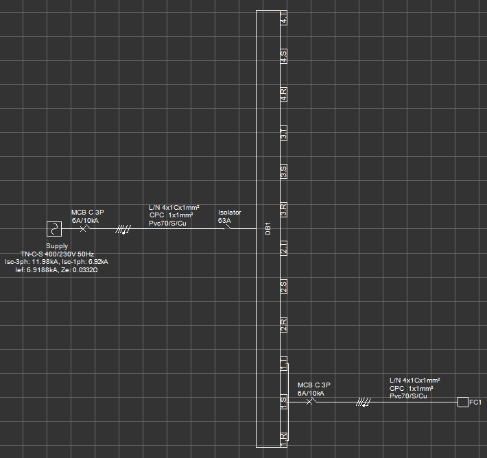
- Main supply orientation - Right:
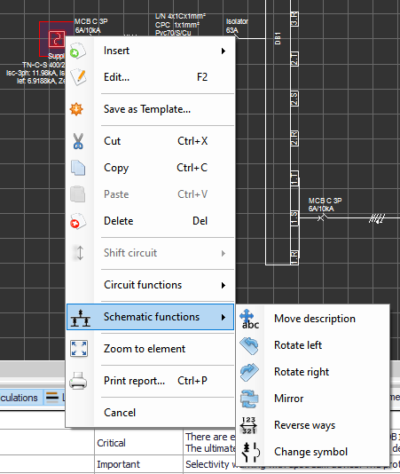
It is important to notice changing the orientation setting will not affect the existing components connected to an existing supply. The setting will be applicable for new components connected to new supplies within the project. In order to change orientation of existing components, the user shall use right-click menu and initiate Rotate left, Rotate right or Mirror commands on any highlighted object.
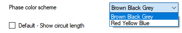
- Phase colour scheme: The user can switch between two colour scheme:
- Brown - Black - Grey
- Red - Yellow - Blue
- Empty way description: By default, ElectricalOM will mark empty ways as "empty" at system tree area. This can be changed by typing in required description inside the text field. This settgin will not affect existing components and will be applied to new components. Below, word "Spare" is used as an example.
- Predefine Cable Display Scheme: The default setting for displaying cable information on schematics is "Make-up" but it can be changed by using the drop down list as desired. This option will not affect existing scheme and will be used for new cables.
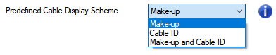
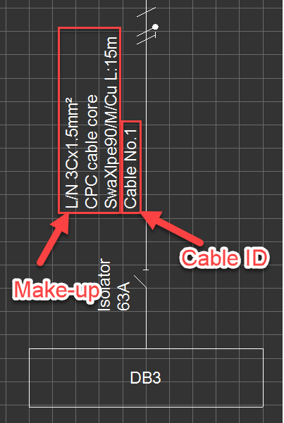
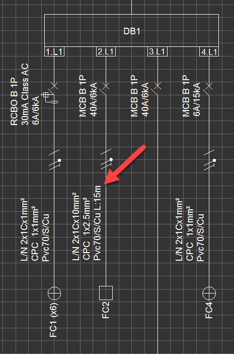
- Make-up: will display Line, Neutral and CPC cross-sections, cable type, and, if enabled, cable length information over the related cable.
- Cable ID: will display the cable ID only over the related cable.
- Make-up and Cable ID: will display both Make-up and Cable ID information over the related cable.
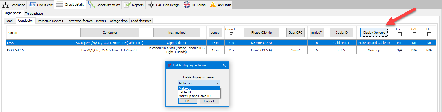
If user wants to change the scheme for a specific cable, Conductor tab under the Circuit details module tab can be used. Cable can be highlighted by clicking to the corresponding row, and then, "Display Scheme" button can be clicked to change cable display scheme as desired. Again, multiple rows can be selected to a bulk change.
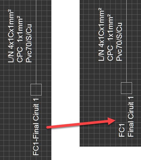
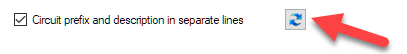
- Circuit prefix and description in separate lines: This option will display prefix and description on two likes rather than a single line.
Once the setting is changed, to refresh the existing components, refresh button must be clicked.
- Switchboard way numbering like DBs: ElectricalOM will number each circuit inserted to a switchboard as an individual way. However, the user may opt to number the ways as if it is a distribution board which will reserve way numbers for all three phases. See picture below for clarification.
- Print inactive/non-powered network with normal colouring: ElectricalOM will print inactive parts in grey and active parts in black by default. If this box is ticked all parts will be printed in black.
- Compact 3ph ways: This option will display 3ph ways as seen on the picture below.
- Set as default Section
- Show cable length: While creating circuits, user needs to define conductor/cable lengths in order to get accurate calculations. As default, this option is disabled but ElectricalOM may be set to show these conductor/cable length data on the schematics as default by checking this tick box. This option affects only new conductors/cables and existing conductor/cable length setting will not be affected.
If the user wants to show or hide lengths for specific conductors/cables, than, Circuit Details Module tab shall be used, please refer to this section for more details.
- Set distribution circuits to compacted mode: This option is used to show/hide final circuits on the schematic. It is disabled as default but can be set as it is enabled as default. This option affects new items only and does not change the state of any existing item.
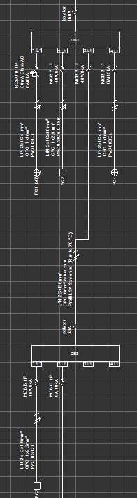
DB1 is in Expanded mode.
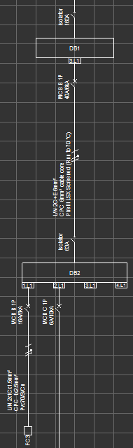
DB1 is in Compacted mode.
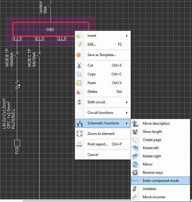
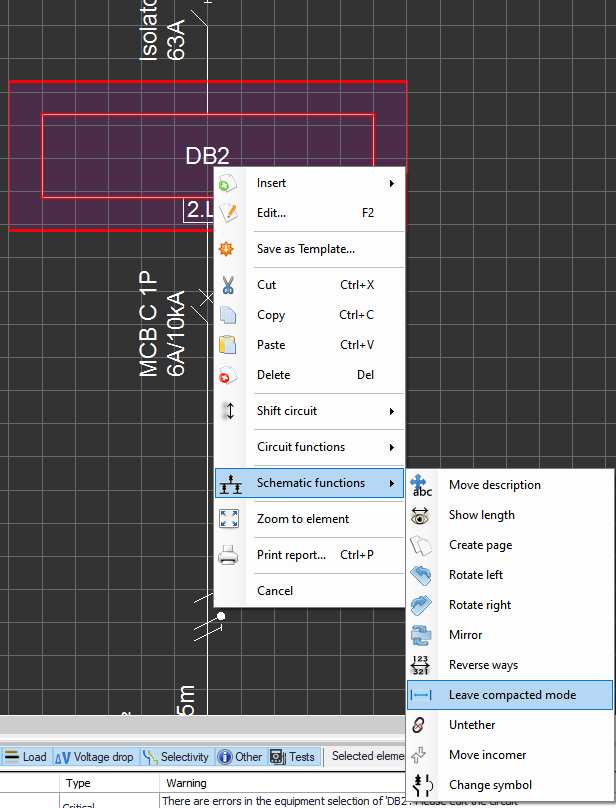
If the user wants to toggle between compact mode and expanded mode, then, right-click menu shall be used. First, the corresponding board needs to be selected, then, from the right-click menu either "Enter compacted mode" (if the board is in expanded mode) or "Leave compacted mode" (If the board is in compact mode) can be selected by the user to switch between modes.
- Tree network multi sources: By default, system tree area will only display the active source. This tick box will set ElectricalOM to display all the sources within the project in the system tree area by default. This option can also be activated via system tree toolbox but this will only affect the active project.
- Predefined frame section: Please refer to Predefined Frame Section.