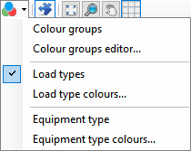
Colouring Method
Colouring method
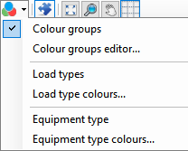
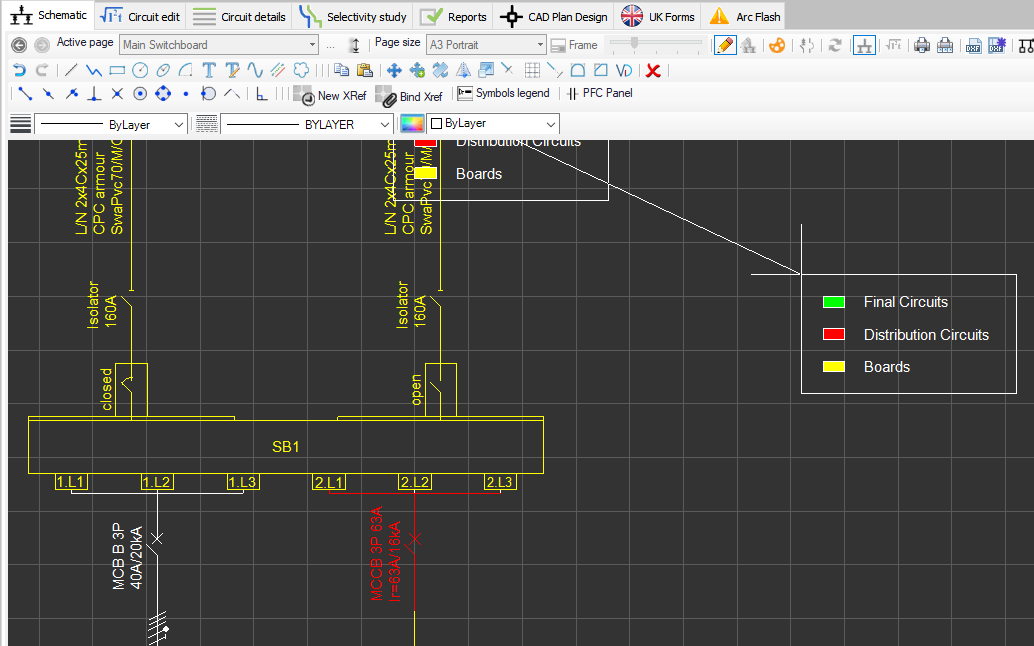
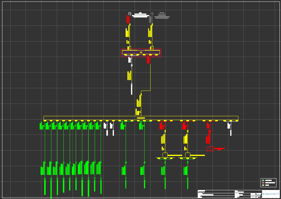
The user may want to indicate different types of circuits by using colours. Circuits can be categorised by: colour group, load type, or equipment type. User must define associated properties before enabling the desired option, otherwise there will be no colours visible on the schematic.
- Colour groups method
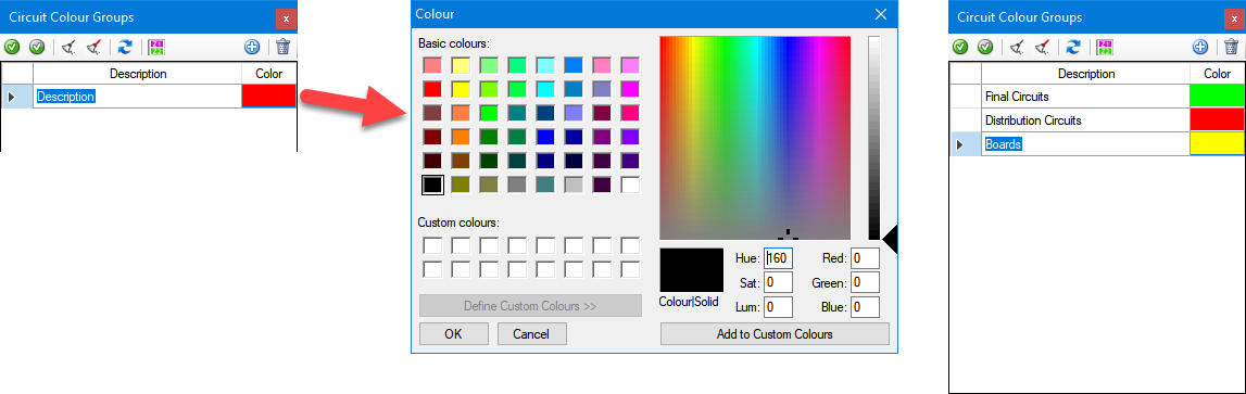
Colour groups option is the first option on the drop down list. First of all, the user has to define groups using the Circuit Colour Groups Editor window which will appear when clicked on Colour groups editor... option.
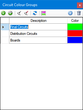
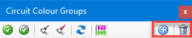
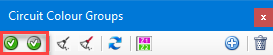
Colour groups can be created using the Add button, and can be deleted by the Delete button located on the top right corner. Circuit Colour Groups windows is a floating windows which the user still have access to the drawing area and make selections.
When Add button is clicked, a new row will be created by ElectricalOM which the user can type in a desired description. The colour can be changed by clicking on the rectangle fill with a set colour under the Colour column. This will open the colour palette. Groups can be created as many as the user requires.
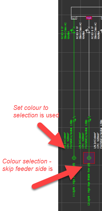
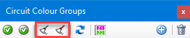
Once the groups are created, the user can select components and assign the selection to a colour group by using either Set colour to selection or Colour selection -skip feeder side button. Colour selection - skip feeder side option will set the selected colour to the selected components leaving the feeder circuit unaffected by the colouring.
When a colour assigned it can also be removed by using Uncolour selection and Uncolour selection - skip feeder side buttons.
Similar to above options, the user must select the components wished to remove colours and click one of the options. Uncolour the selection - Skip feeder side option will leave the feeder colour unaffected by the options.
Refresh button will refresh the drawing area to apply the changes made by the user after the last refresh, and Insert Colour Legend will switch to the drawing area enabling the drawing mode and waiting for the user to pick a location for colours legend.
- Load types method
Second option is the load type method. This method will colour only the boards and not other circuits.
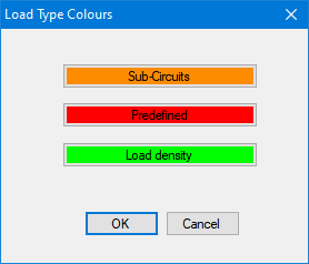
Load types can be selected from Circuit Edit module, where colours for each type can be selected by clicking on Load type colours... option. Once the Load Type Colours window is displayed, then, clicking of the load type will call the colour palette window. The user can associate a colour from this menu to a load type which ElectrcialOM will use to represent associated load type on the schematic.
- Equipment types method
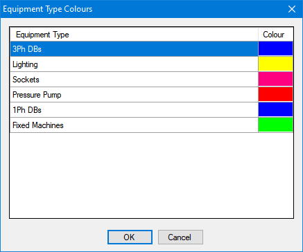
Third option will let the user to colour the circuits according to their equipment types. Equipment types can be defined by following the steps specified under Equipment Types title in Other details Tab section and will not be discussed here. The user must use Equipment type colours... option to define colours for each equipment type.
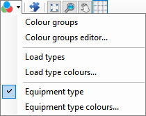
Equipment Type Colours window will list the equipment types defined by the user with a colour box in front of each row. Clicking on the colour box will call the colour palette windows which displays colour options for the user to select.