Multiple Converter Scheme
ElectricalOM is capable of modelling multiple rectifiers working in parallel. In order to model such a scheme, the user needs to follow the steps below:
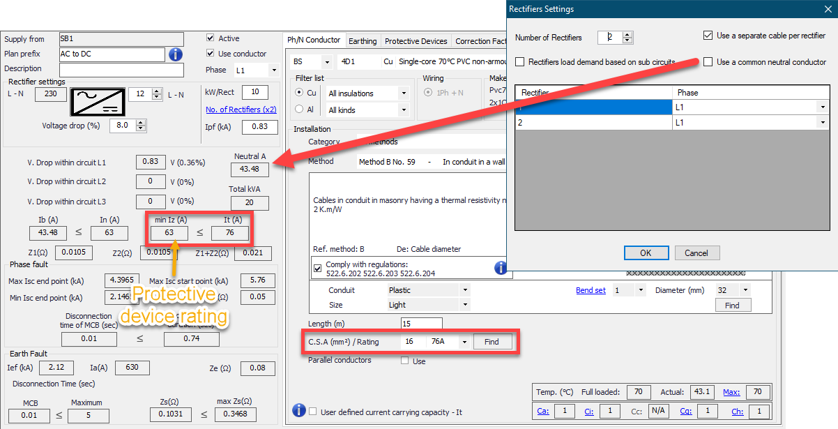
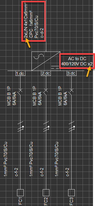
- Click on the Converter component and access to Circuit Edit tab. Click on the No. of Rectifiers link to open the Rectifiers Setting window.
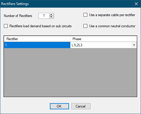
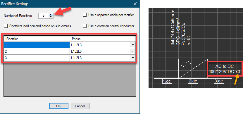
Changing the Number of Rectifiers field will ad or remove rectifiers from the circuit. This can be visually followed via the rectifier list, where the rectifiers will be numbered and the type of the rectifier will be displayed (3Ph or 1Ph). Also, the designation will be modified to indicate multiple rectifiers.
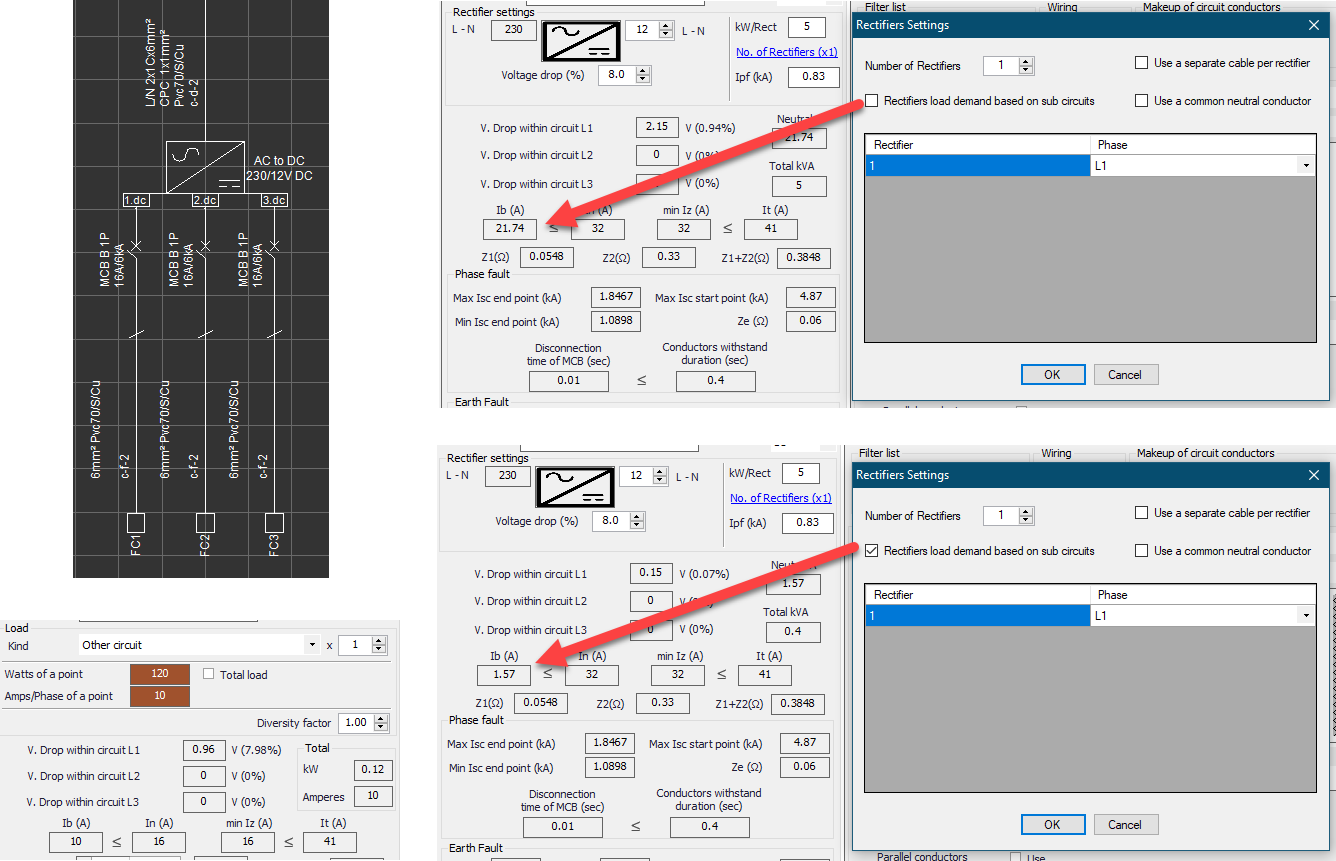
Rectifiers load demand based on sub circuits: The design current of the rectifier circuit will depend on the power of the rectifier set by the user, however, if this box is ticked, ElectricalOM will consider the connected load to set the design current.
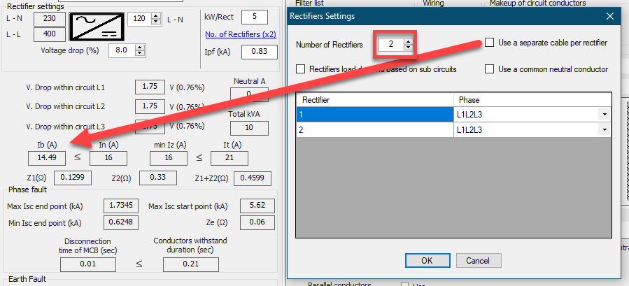
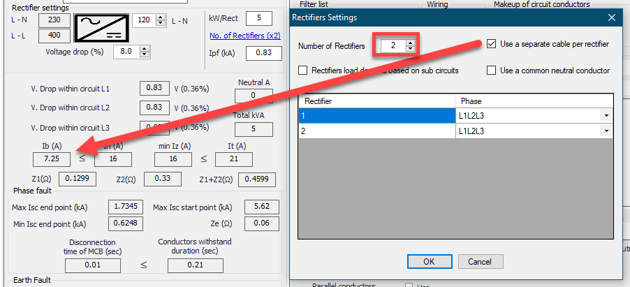
Use a separate cable per rectifier: When the number of rectifiers increased, ElectricalOM assumes a single feeder cable as default, however, the user may set ElecricalOM to model the rectifiers as if they are fed by separate conductors by ticking this box.
If separate cables are used, then, ElectricalOM will divide the design current to the number of rectifiers and base the calculations on this value.
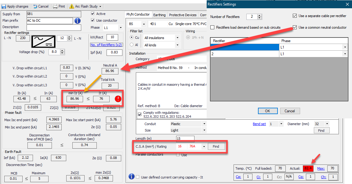
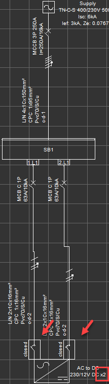
Use a common neutral conductor: This option is only applicable when the Separate conductor for each rectifier is used together with Parallel Source Operation feature. In this arrangement, ElectrcialOM will display each conductor connected to the rectifier via an individual switches. ElectricalOM will assume separate neutral conductor as default but the user may combine the neutrals by ticking this box. The neutral current will be calculated accordingly by ElectricalOM. This is apparent with 1Ph components.
ElectricalOM will monitor the neutral current whatever the setting is and will suggest required warnings if any issues arises when the neutrals are combined.