Parallel source operation...
Parallel source operation...
ElectricalOM lets:
- Multiple sources to be modelled as parallel if they are connected to certain components: Switchboard, Junction Board, and Transfer Switch
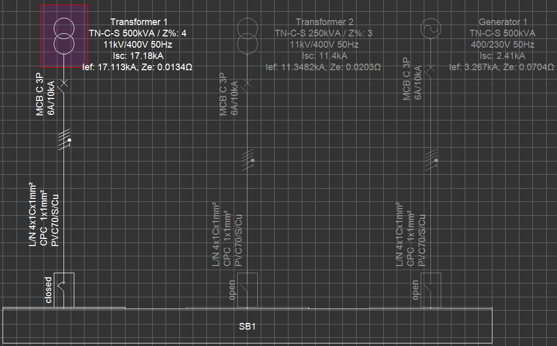
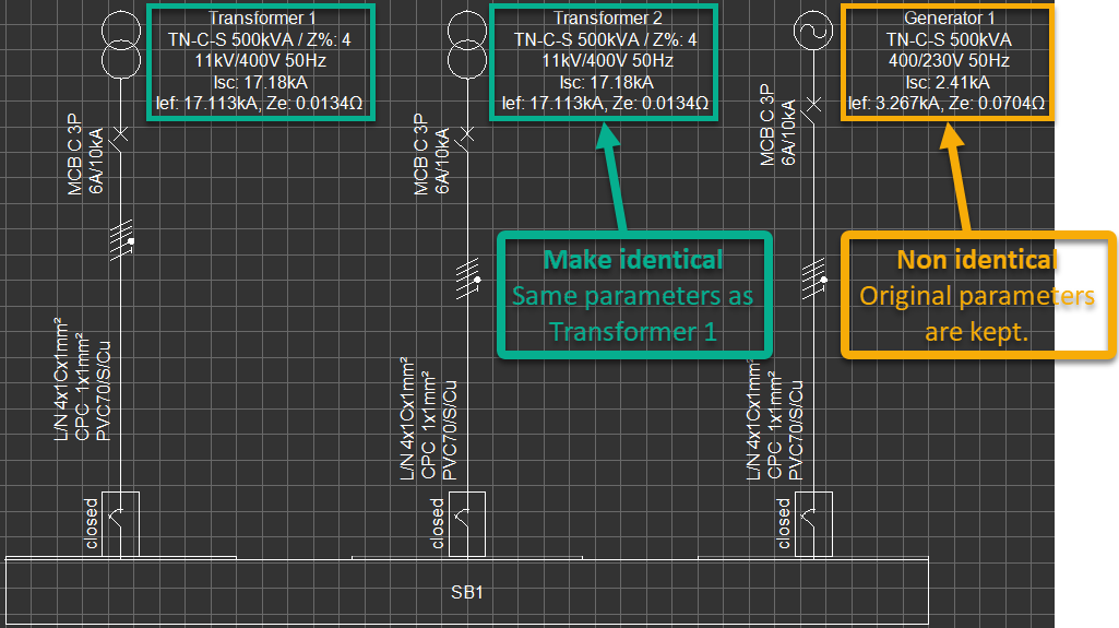
First, the user must make sure the active source is one of the sources which are going to be modelled as parallel. In the case shown below, Transformer 1 is the active source, and it is going to be one of the parallel sources.
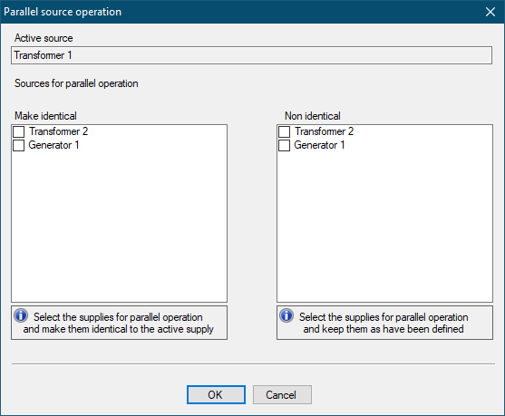
When Parallel source operation... option is selected, ElectricalOM will list all the sources which are possible to run in parallel together with the active source on two separate fields: Make identical, and Non identical.
In the case below, the active source is Transformer 1 and possible sources which can be run in parallel are Transformer 2 and Generator 1. Each source has different characteristics; Transformer 1 is a 500KVA transformer, Transformer 2 is 250 KVA transformer and the third source, Generator 1, is a 500KVA generator.
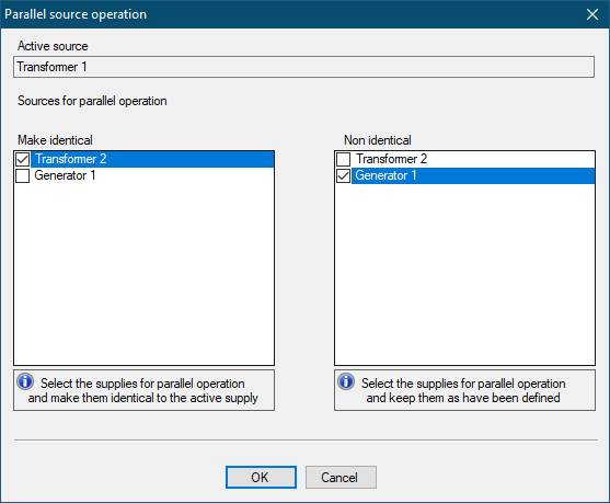
Once the required sources are selected and OK button is clicked, all the sources will be shown as active, with related switches in closed position, and all the settings will be identical except the given names for the sources.
To remove a source from parallel operation, Parallel source operation... can be used again. The source needed to be removed from the parallel operation can be deselected from the Sources for parallel operation list, and ElectrcialOM will remove this source from parallel operation.
- Multiple feeder circuits to be modelled as parallel supplies as long as the feeders are originated from the same distribution node
This option is available for Switchboards, Junction Boxes, Transfer Switches, Transformers, UPSes, and Converters only. In order to model a component with parallel feeds, a component with multiple feeders must have already been established.
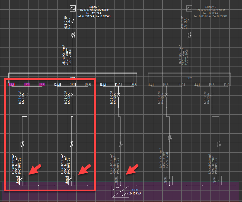
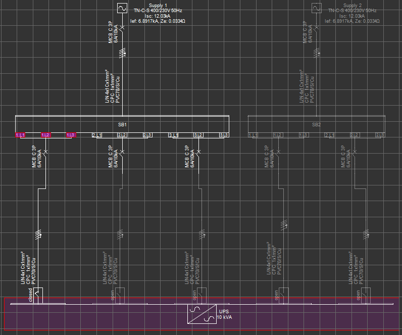
As an example we will consider a UPS fed by the panels, SB1 and SB2, which are also fed by two separate sources, Supply 1 and Supply 2. By default, only one supply (unless they are set as parallel sources) and only one feeder can be active at a time. In the case shown below way no.1 of SB1 of Supply 1 (switch in closed position) is the active supply to the UPS.
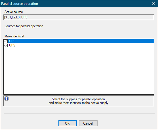
We will select the UPS, which will also select the active feed, and call the Parallel source operation... window. ElectricalOM will list all the supply points which are available to work in parallel with the active supply circuit. In the case below, the active supply circuit is 1.L1, 1.L2, 1.L3 of DB1 (3 phase connection) and possible parallel circuits are way no.2 and way no.3 of DB1. The circuits from DB2 are not listed since Supply 2 is not the active supply and SB2 is inactive. Now, we can tick the ways we want to set as parallel with our original feed, SB1 way no.1, and click the OK button.
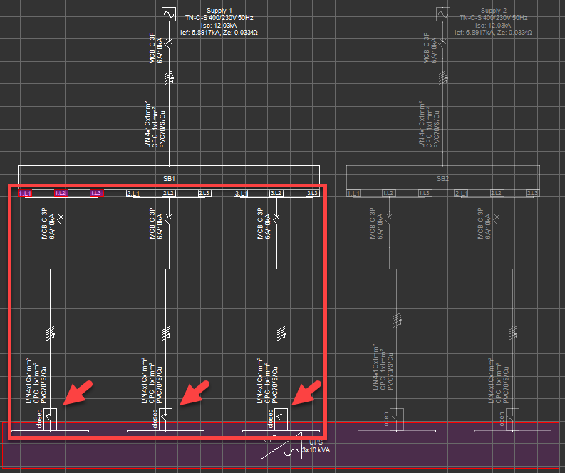
As can be seen from the picture below, SB1 way no.s 1, 2, and 3 are all running in parallel and feeding the UPS after the parallel source operation setting.
In order to set circuits originated from SB2 to feed UPS in parallel too, we need to activate the Supply 2, and repeat the procedure. Bear in mind this will not activate both panels. In order to achieve this, sources Supply 1 and Supply 2 must be set as parallel too.
The user may select as many circuits as required to work in parallel by simply ticking the tick boxes next to the circuits. Once the OK button is clicked, all the supplies selected will be active and related switches will be in closed position. Circuits which are not selected will not be included in the parallel source operation scheme.