Motor Settings
Motor settings is a tab where motor related settings are located. If the user selects a load type contains a motor, the this tab will be displayed amongst other tabs, if the circuit does not have a motor then this tab will not be visible.
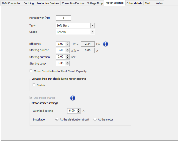
The user can define the power of a motor directly by using the Horsepower (hp) field which in turn will redefine the Output Watts/point field, which is located in calculations section of the Circuit edit module, accordingly. In the same manner, defining Output Watts/point field will update the Horsepower (hp) field.
There are various types of connections the user can pick using the Type drop down list which are listed below. Direct On Line option is selected, the user may opt not to use a motor starter and so the calculations will be based on the design current. All other options will automatically tick the Use motor starter tick box and let the user to set an overload current and a location for the starter. In the case of a motor starter is used, the calculations will be based on overload setting. The location od the motor starter is only important when a Star Delta starter is used.
- Direct On Line
- Soft Start
- Auto Transformer (Only available for three phase motors)
- Start Delta (Only available for three phase motors)
- VSD (Only available for three phase motors)
Usage drop down list contains General and Lift options which will affect the diversity settings only.
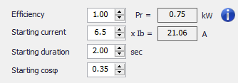
The motor specifications are defined at the Specifications and Calculations area by the user. The rated power and starting current of the motor will also be calculated and displayed by ElectricalOM using the user set data.
Motor Contribution to Short Circuit Capacity tick box (Only available for three phase motors) is accommodated in the Specifications and Calculations area. If this option is enabled, then, ElectrcialOM will recalculate the Max Isc end point (kA) value (see, Circuit edit module's Calculations section) accounting for the motor contribution.
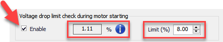
Voltage drop limit check during motor starting, if enabled, will ensure the voltage drop during the starting of the motor will stay below a set value. When the user ticks the Enable box, ElectricalOM will display voltage drop percentage under current conditions and also enable the Limit (%) field for the user to define a voltage drop limit for this circuit during the motor start. This voltage drop limit will only be considered for the starting duration of the motor, which is set by the user above, and will not affect the voltage drop limit of the circuit under normal conditions.
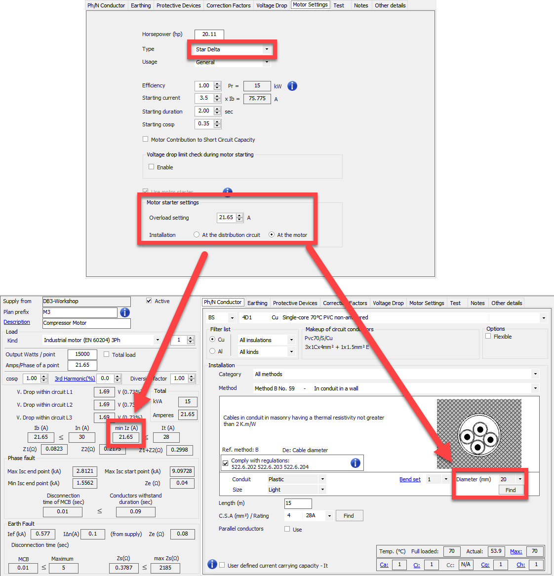
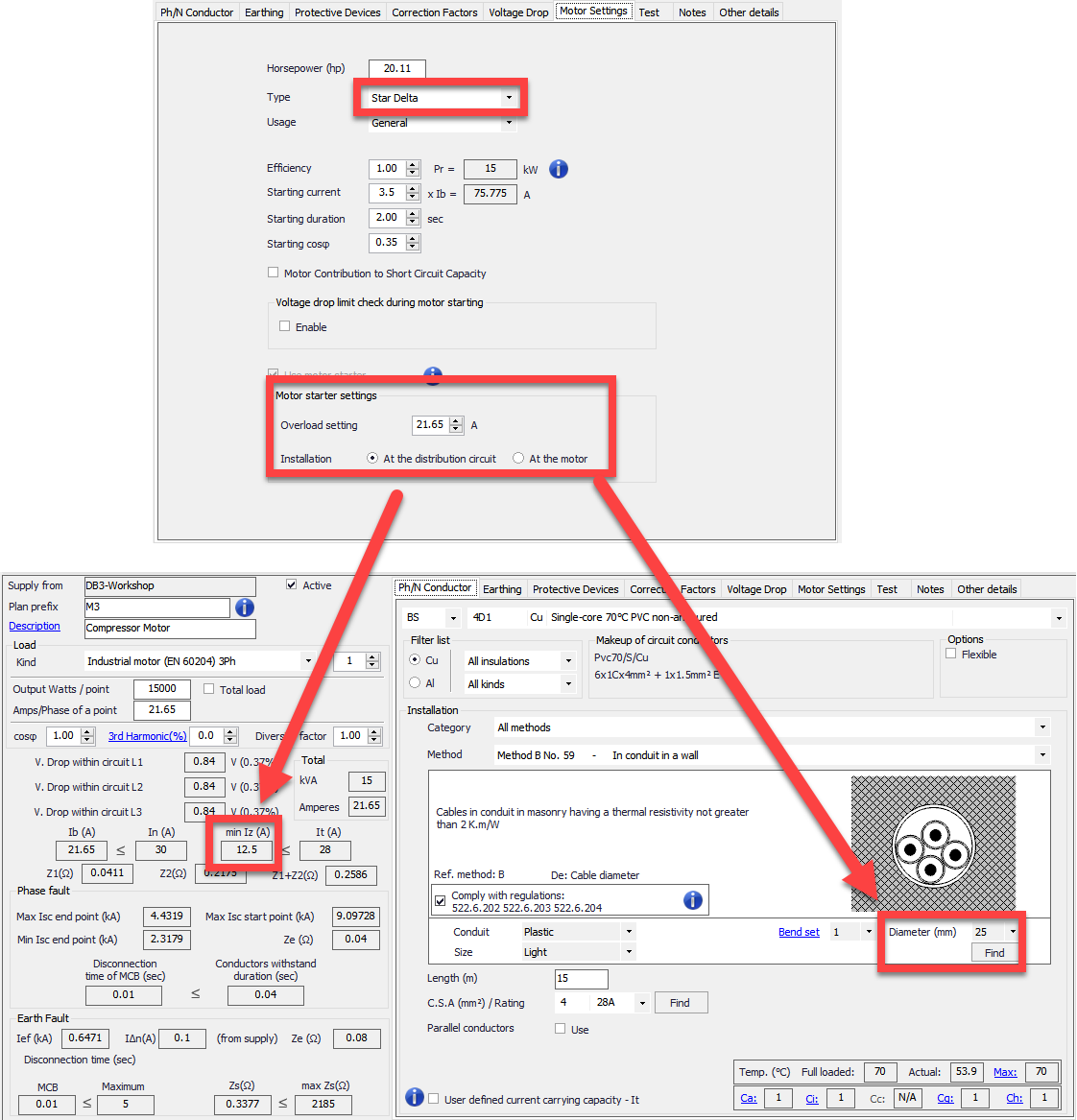
Motor starter settings section accommodates an overload setting and a location setting for the starter. The overload setting represents the setting on the motor starter itself and it will be used for cable sizing calculations instead of the rating of the circuit protective device. Installation which represents the location of the motor starter is only required if the motor starter is a Star Delta starter. The user must to select the correct location for the motor starter.
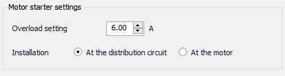
The reason the user must specify the location of the starter when Star Delta motor starter is used is because ElectricalOM will use this setting to calculate the min Iz value and required conduit diameter. If the starter is located at the distribution node, then, ElectricalOM will assume two sets of cables/conductors running to the motor location from the origin of the motor circuit which will share the drawn current by the motor. If the starter is located at the motor location, then, ElkectrcialOM will assume only a single cable/ a single set of conductors running from the origin of the motor circuit to the motor location.