Draw Symbols Array
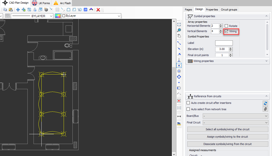
It is possible to create a rectangular array using this option. A symbol must be selected prior to clicking on Draw a symbol array button. Horizontal and vertical elements values can be set before selecting a start point but also be modified dynamically as long as a second point is not selected. A second point can also be specified using the Command line area, by typing in a coordinate (e.g. X,Y).
Similar to Draw symbol settings, Rotate option will let the user to rotate the array after it is finalised by defining a second point, and Wiring option will automatically wire the symbols together.
Symbol Properties will affect each element of the array. Label field is used to set a label for the array and it will be displayed next to each element of the array. Elevation will set all the array elements' height to the value entered. Final circuit points will set a quantity for each element of the array.
Once the array is finalised, each component will act as individual and not as a group.

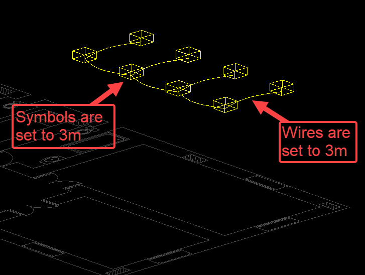
As a representation of elevation settings, please see the picture below which is an extract from 3D view of CAD Plan Design module. Here, the symbols are set to 3m above the floor plan, and wiring is also set to be at 3m.
