Draw Symbol
As mentioned earlier in Symbols Area section, a symbol can be inserted by drag&drop feature of Symbols Area. Once a symbol is dragged on to the drawing area, side panel will display Draw symbol settings automatically. However, it is also possible to select a symbol and then to clink on Draw symbol button to switch to settings. Settings displayed here are not associated with the symbol itself but with the item the symbol will represent on the drawing.
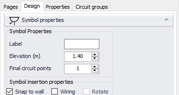
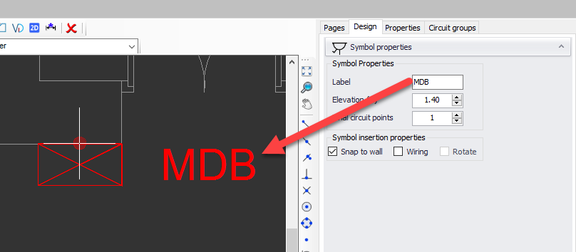
Label area is a text based input and it will be displayed next to the symbol.
Elevation (m) represents the height of the component symbol will represent referenced to Z=0. This value will be used to estimate cable lengths and it will help CAD Plan Design module to properly display the symbol on 3D view.
Final circuit points represents the quantity of a component which will be represented by a symbol. This value will be used while populating materials list, etc.
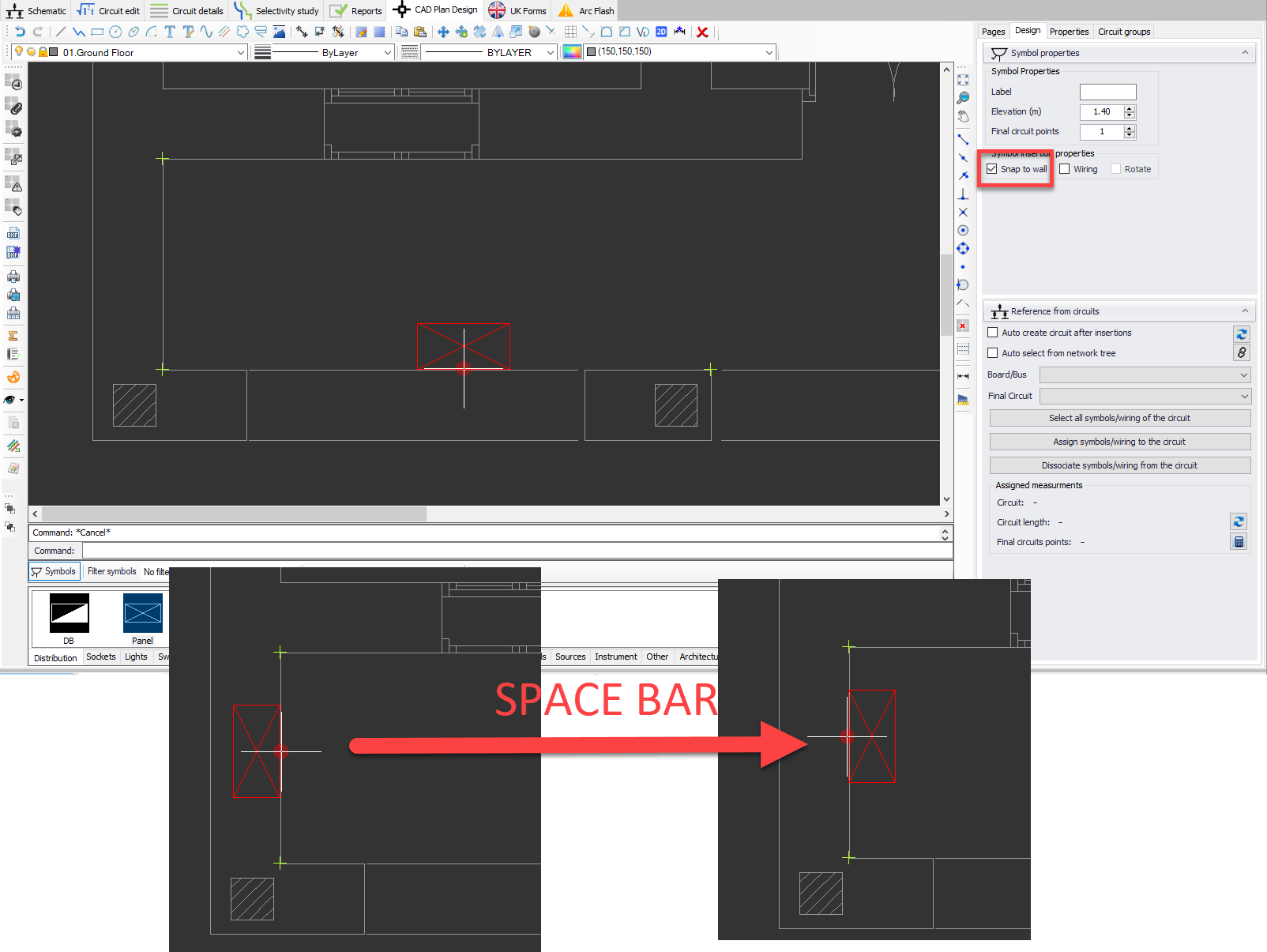
Snap to wall will rotate the symbol to match with the angle of the closest line. The symbol can be flipped by pressing the space bar.
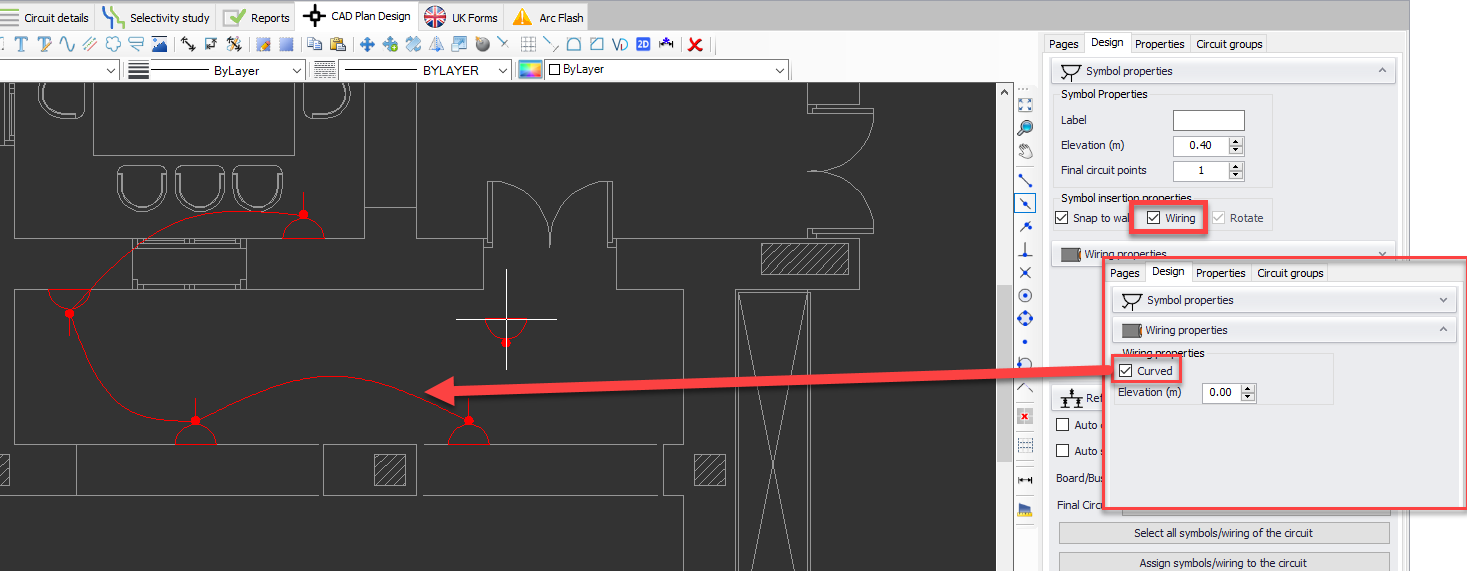
Wiring option will automatically wire inserted symbols as they are inserted. Once this box is ticked, Wiring properties will be displayed on the side panel where the user may set a drawing style, curved or straight lines, and wiring elevation in meters.
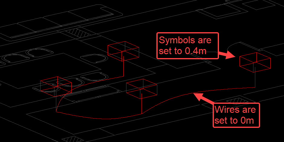
As a representation of elevation settings, please see the picture below which is an extract from 3D view of CAD Plan Design module. Here, the symbols are set to 0.4m above Z=0, which is the floor plan, and wiring is set to be at 0m.
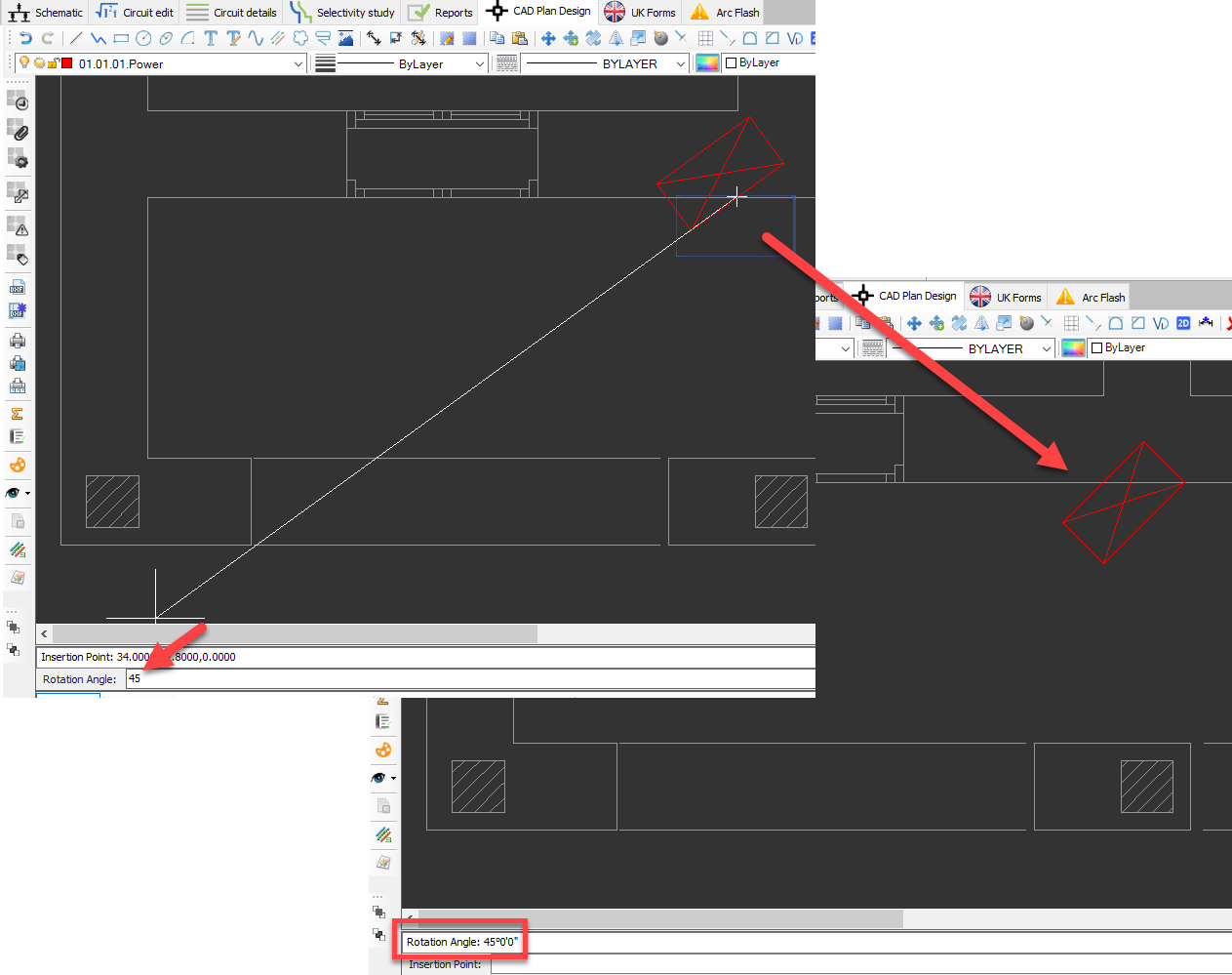
Rotate will let the user to set a rotation after a symbol is inserted. In order to be able to use this option, Snap to wall option must be unticked.
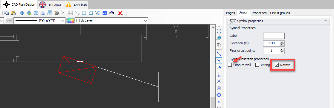
A rotation angle can also be specified using the command line area and pressing Enter.