Schematic Menu
Schematic
- Auto layout mode: This controls how the new components are inserted to the schematic. If this is disabled, ElectrcialOM will insert components as default arrangements and will not check and rearrange overlapping components.
- Make all manual mode layout: If this option is executed, then, ElectricalOM will insert new components similar to the case when Auto layout mode is disabled ignoring previous settings.
- Refresh page layout/Global refresh layout: If the locations of elements are modified by the user but it is needed to go back to default layout, this option will move elements to their original locations. This option is only effective on the current page. If a global refresh is needed, then, Global refresh layout can be used to apply refresh to all pages.
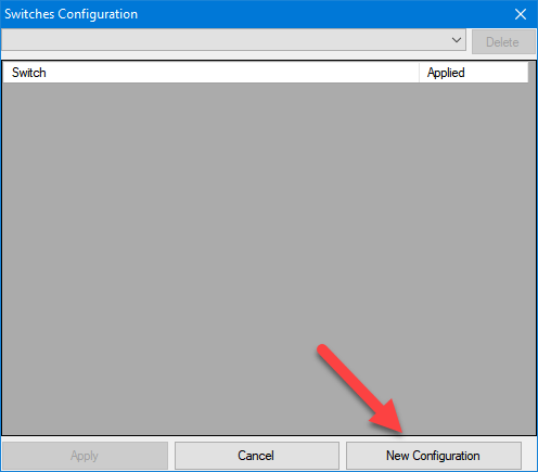
- Switches configuration: ElectricalOM lets the user to define multiple configuration scenarios if the system contains switches like it is demonstrated below. In order to save a configuration. user shall set it up the required scenario and then save it.
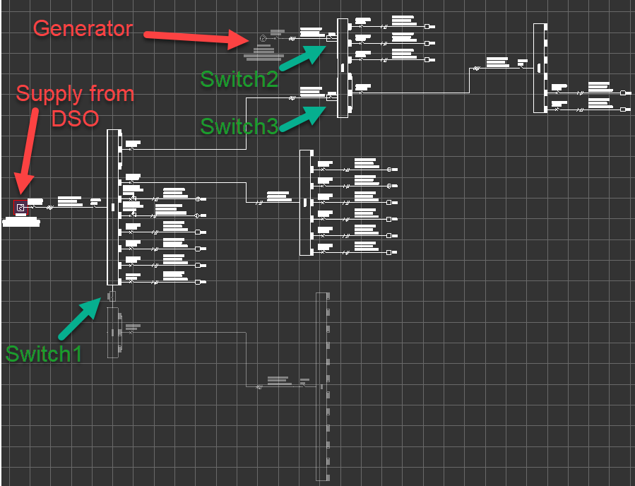
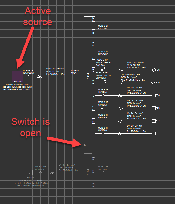
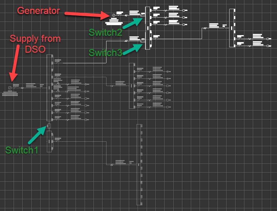
Above, the supply from DSO is connected to SB1-1. SB2-1 is a switch board with no supply but it is coupled to SB1-1. Then, there is a generator connected to SB1-2 as immediate power supply. First scenario has the DSO supply available but SB2-1 is not coupled, i.e. Switch1 is open. Also, the generator of offline, i.e. Switch2 is open and Switch3 is closed.
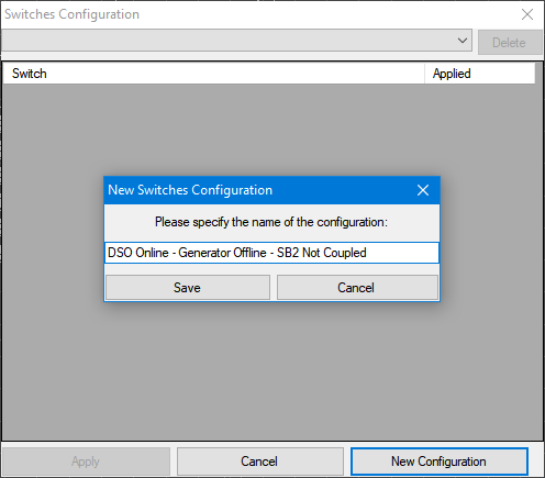
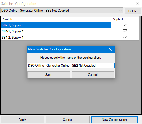
The user can use Switches configuration... window and select New Configuration to save this configuration.
ElectricalOM will ask the user to define a name for the configuration to be saved.
A new configuration can be set up by using the switches. A coupled switch (Switch1) can be opened or closed by double clicking on it.
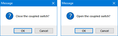
Depending on the active source, opening or closing the switch will determine the separated part and ElectrcialOM will inactivate this part of the system.
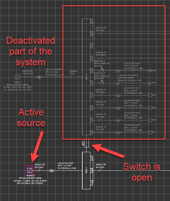
Other type of switches will be available only if this part of the system is active. Once related part is activated, double click will only be available for opened switches. If a closed switch is double clicked, Circuit edit module will be displayed for the board which the switch is connected.

If the switch is controlling a supply to a board, and there are multiple supplies, closing a switch will open all other switches.

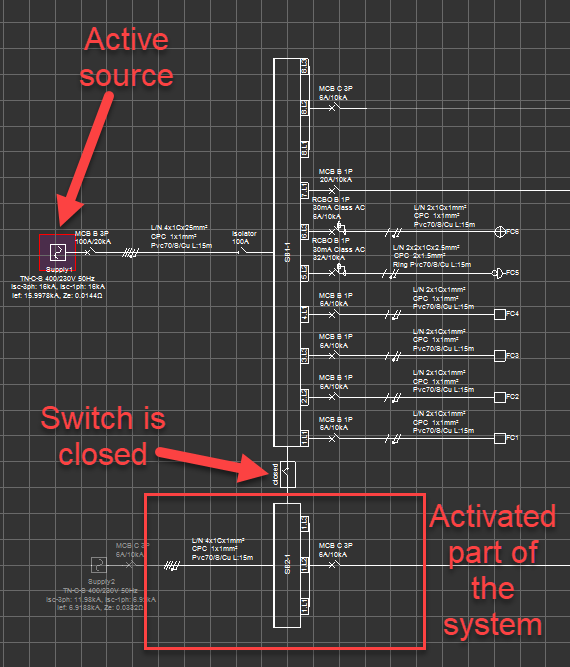
The same system as above is reconfigured as below using the switches and the new configuration is saves the same way as described above.
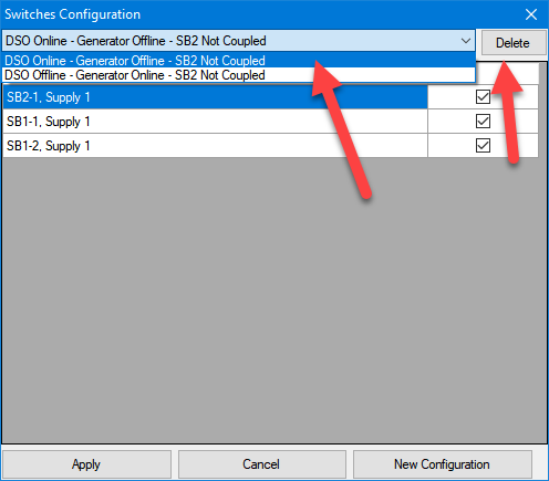
Switch configurations are saved as a drop down list by ElectricalOM and can be selected by click on the arrow next to the description area. Once the required switch configuration scenario is selected, clicking Apply will set the switches as saved.
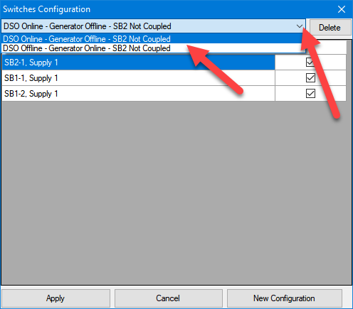
If the user wants to delete a specific configuration, then the configuration wanted to be deleted shall be selected prior to clicking on Delete button. Deleting a configuration cannot be undone.
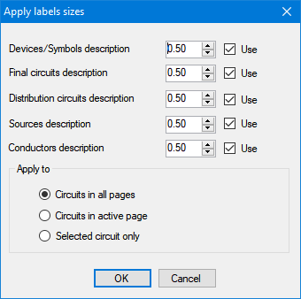
- Apply labels sizes:This option is used to change the font size of the labels. Changes can be applied to objects on the current page, or object on all pages, or selected circuit only.
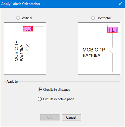
- Apply labels orientation: This option will help the user to modify the orientation of the labels. Changes can be applied to the current page or all pages. This is similar to Reverse label orientation option but for multiple objects, refer to Schematic Functions.