Manual selectivity study
This is a feature which lets user to perform a selectivity study without generating a model. When it is selected, a new window will pop up, Manual Selectivity Study.
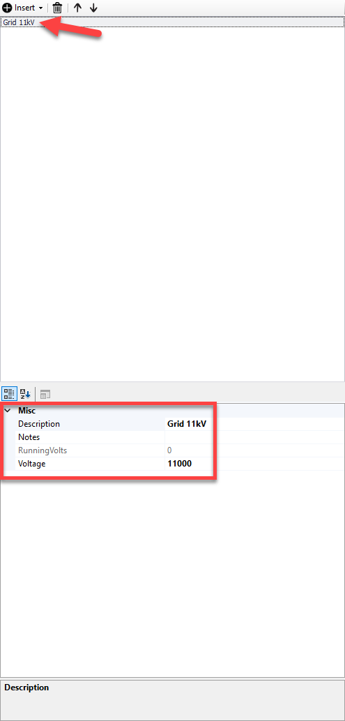
At the top toolbar, if this is the first study, only option is to select New study option. As soon as this button is clicked, a source is inserted to our study. Items can be seen at the top left hand side panel. The source will be Grid 11kV by default.
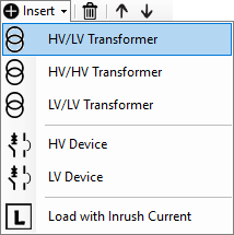
User is expected to insert each protective devices starting from the source up to the load. This is performed by using the Insert option.
Once a component is inserted, bottom left hand side panel will display properties of the selected component.
- Current multiplier (only for loads) sets the inrush/starting current by means of a multiplier.
- Derating can be used to define a de-rating factor.
- Description can be modified as per user's requirements.
- Inrush Duration and Inrush multiplier (only for transformers) will define the inrush characteristics of the selected component.
- Duration (only for loads) will define the inrush/starting duration of the selected component.
- Device will display the selected component.
- Exclude option can be set to False or True. If this is set to True, then ElectricalOM will exclude this component from the active study.
- Notes can be used as per user's wish.
- Rating KVA (only for transformers) sets the rated value of the selected component.
- Parallel option will tell ElectricalOM how many devices there are on the circuit. All devices will be assumed to be identical.
- Running volts will display the voltage at the selected component.
In the example below, our load is a motor. This motor is fed from a board which is connected to the source. So, we firstly inserted a transformer, then two protective devices. First one, a 250A MCCB, as the incomer to the main board, MDB. Then we have a 16A Type C MCB protecting the motor circuit. we have a motor protected by a C type MCB, which is fed from a board also protected by a 250A MCCB. We also have the DNOs fuse, a 500A fuse.
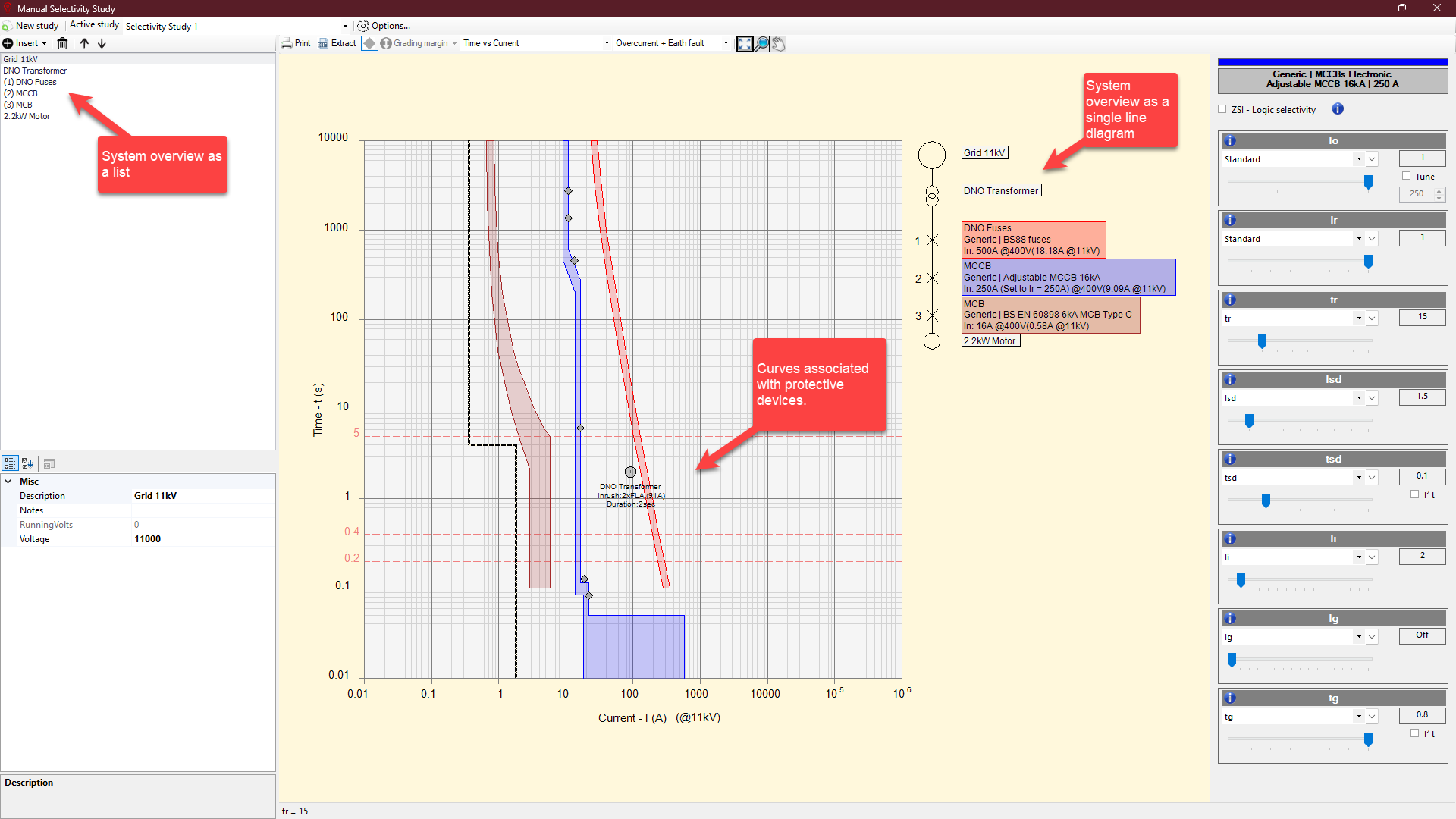
Devices can be selected both from the left hand side panel, and single line diagram by clicking on a component. If there are any settings related with that component, they will be displayed on the right hand side. Sliders can be used to adjust any setting. Also, grip points (small diamond shaped indicators) can be used to adjust associated settings instead of the sliders.
Once the system is modelled, toolbar can be used. The options are:
- Print button starts the print window.
- Extract will display a browser window where user can select a location for a .dwg file to be saved.
- Show/hide device setting grips will enable or disable the grip points of adjustable devices.
- Grading margin
- Curve selection drop down list can be used to switch between Time-Current curve, Let-through Energy-Current curve, and Limited current-Current curve (if applicable).
- Fault selection drop down list has no function.
- Zoom all button will zoom or unzoom curves to fit the curve drawing area.
- Zoom window button will zoom in to user's selected area. Once this is clicked, a rectangle can be drawn within the curve drawing area using mouse. This rectangle will define the zoom area.
- Pan button will enable pan action. User can use the mouse to pan within the curve drawing area by holding the mouse left button.
Each manual study can be saved to be accessed later on, however this will save with the current project. So, in order to re-open a saved study, user needs to open the project the study saved with first. Options button is used to save a study.
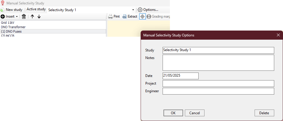
Each filed can be filled in by the user as required. OK button will save the study.
An existing study can be deleted by clicking on Delete button.