Toolbar No.1

Toolbar 1 is focused on drawing, and manipulation of items in the drawing area. Keyboard key F8 will enable or disable the orthogonal mode which only lets the user to draw on X or Y axis regardless of the cursor position.
Toolbar No.1 buttons are, In order from left to right:
- Undo/Redo: These buttons take back/repeat the last action. They can be used multiple times to take back/repeat multiple actions.
- Draw Line: This button is used to draw a line on drawing area.Once this button is click ElectricalOM will wait for an input from the user to define the starting point. It can be done either by selecting a point from the drawing area by clicking on the left mouse button or entering a coordinate using keyboard.
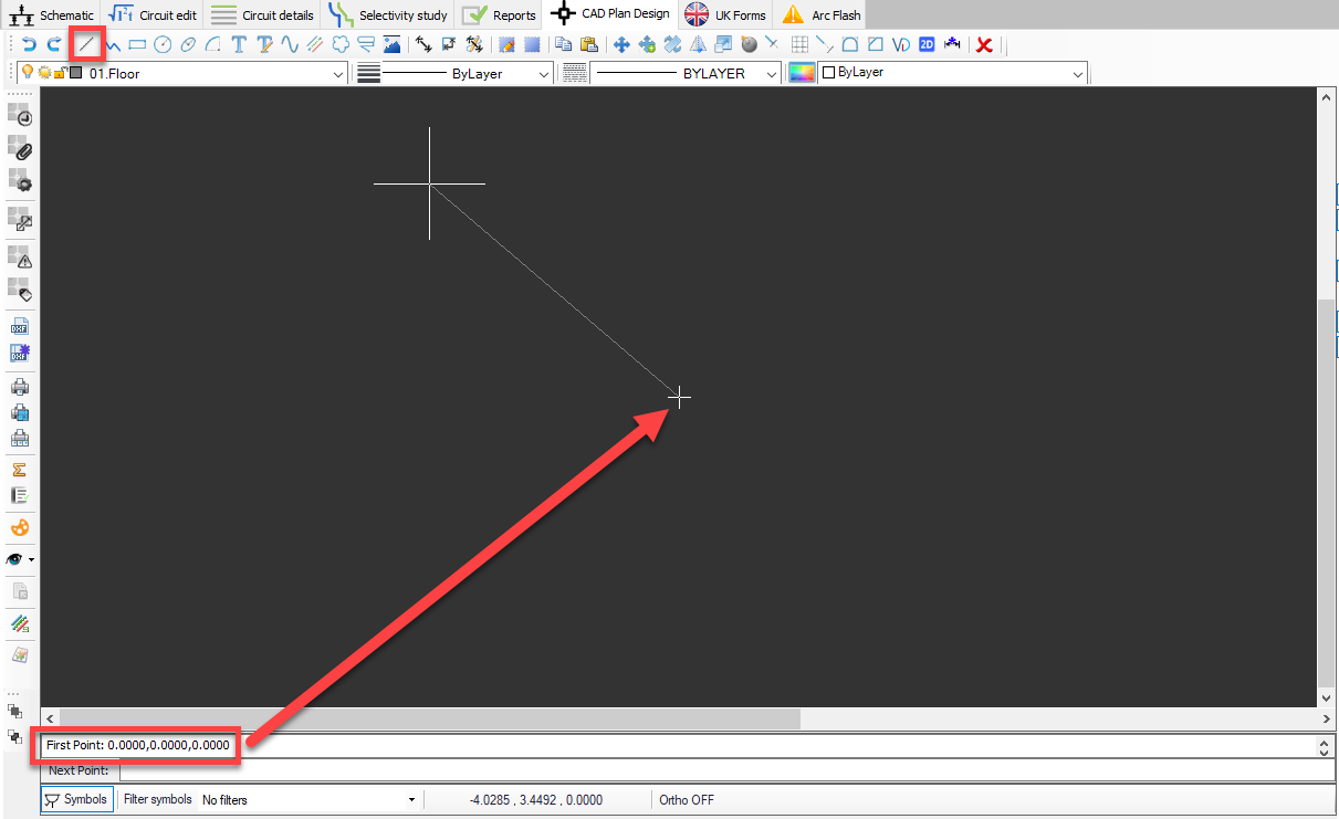
It is possible to continue drawing lines by selecting points continuously or entering coordinates one after the other. Esc key will stop the process.
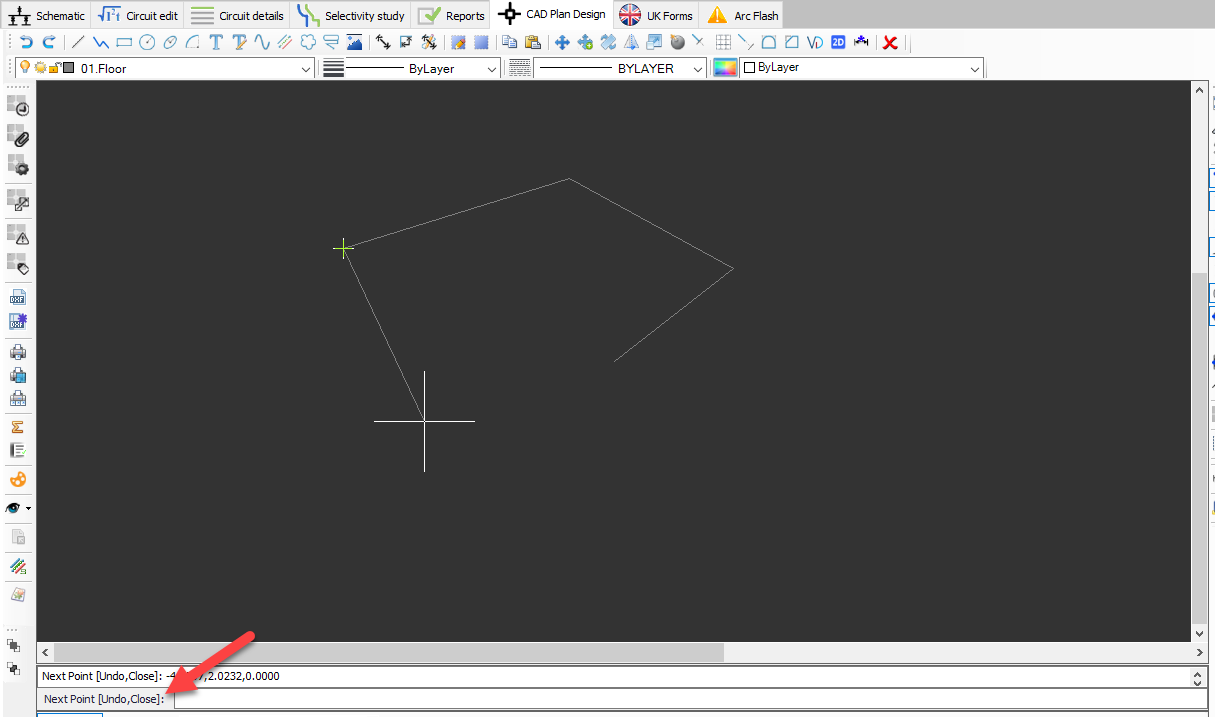
- Draw Polyline: This button is used to draw a polyline on the drawing area. Usage is similar to drawing a line, however, the result will be a single item rather than multiple lines.
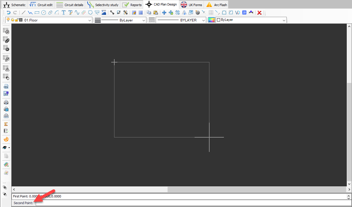
- Draw rectangle: This button is used to draw a rectangle on the drawing area. Once clicked, ElectricalOM will first wait for a start point entry, then, for a second point entry.
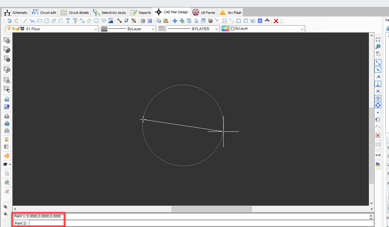
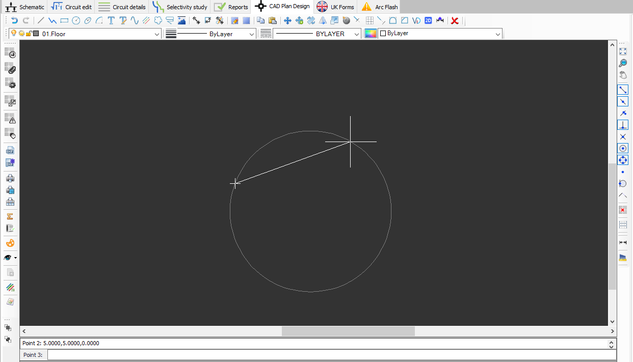
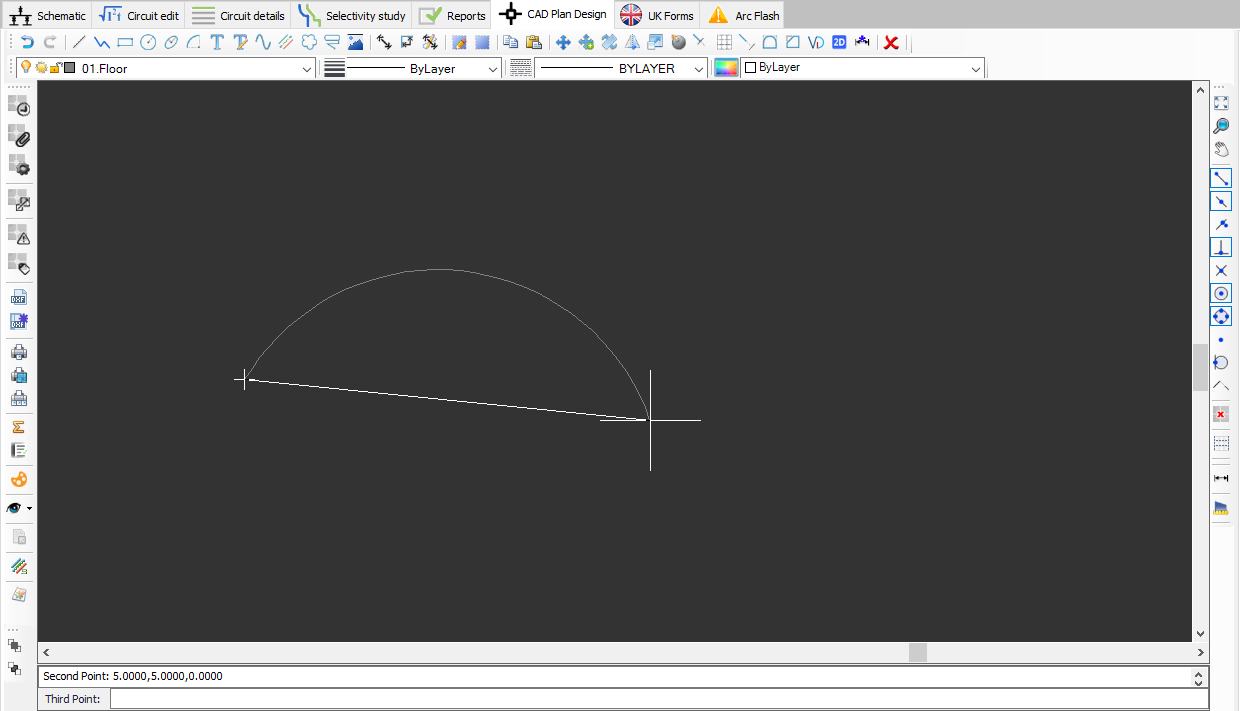
- Draw circle: This button is used to draw a circle on the drawing area. Once clicked, a centre point entry will be expected, however, the user may force a 2 point or a 3 point definition of the circle by typing in 2P or 3P using the keyboard. If centre point is defined, then, ElectricalOM will wait for a radius.
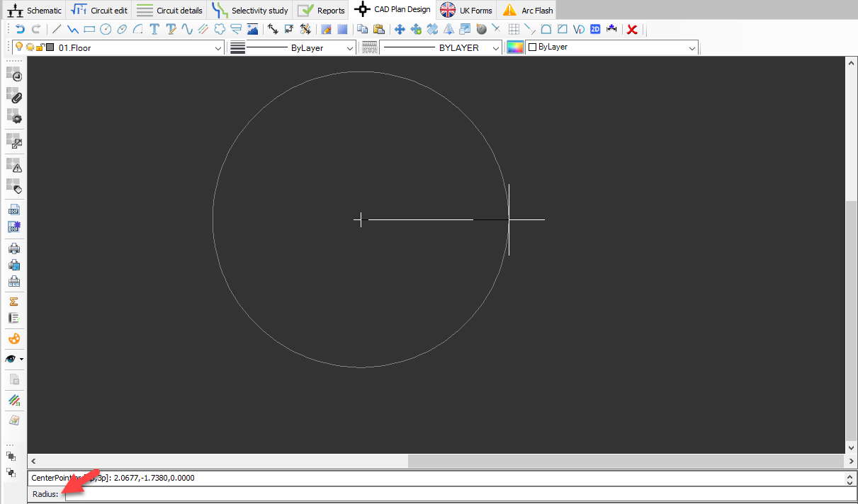
2 point option will wait for a Point 1, and than, for Point 2.
3P option will expect three points to be defined by the user to draw a circle.
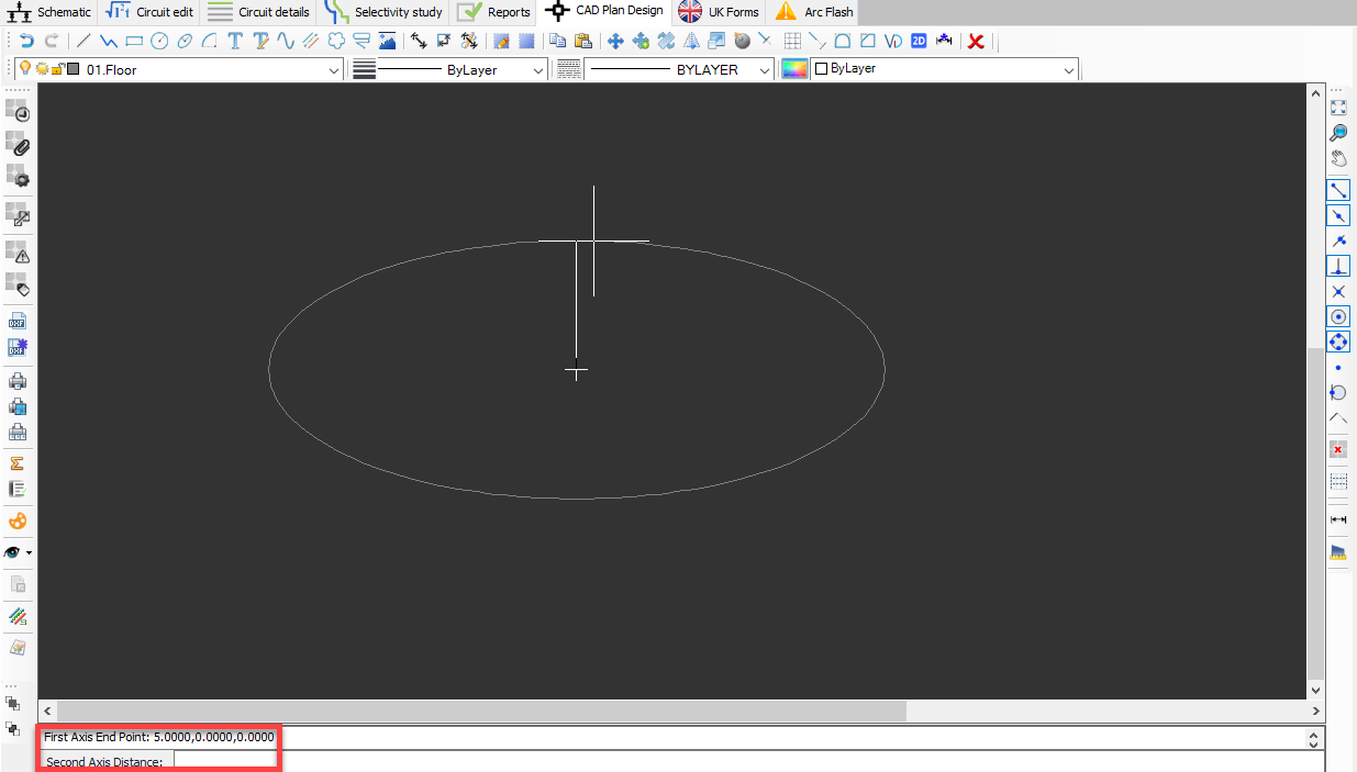
- Draw ellipse: This button is used to draw an ellipse on the drawing area. ElectricalOM requires a start point, a First axis length, and a second axis length to be defined by the user.
- Draw arc: This button is used to draw an arc on the drawing area. Arc has three ways of definition. Default way will expect the user to define a centre point, a radius, a start angle and an end angle. 3P option will require a start point, an end point and a third point to finalise the drawing.
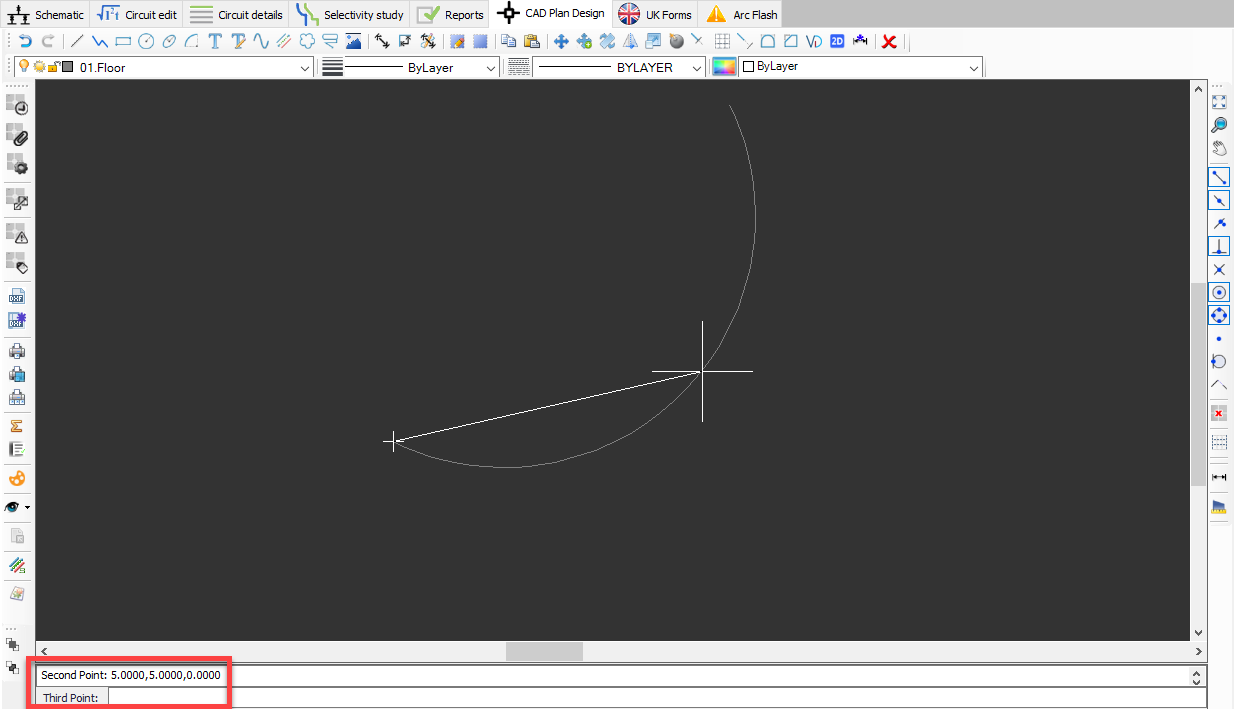
E3P option will also requires three points to be defined, however, this time the last entry is the end point.
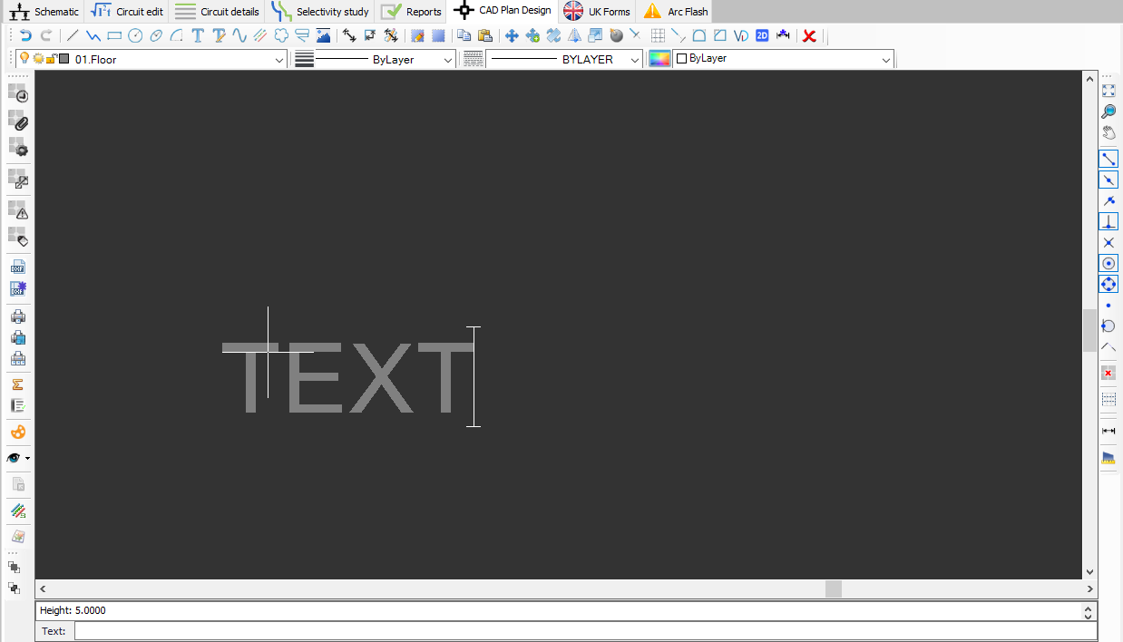
- Insert text: This button is used to insert a text on the drawing area directly. Once clicked, the user must define the insertion point for the text and the height of the text. Then, required text can be entered using the keyboard. Once the user finished typing, right click will finalise the process.
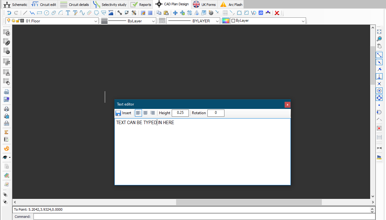
- Insert text with editor: This button is used to insert a text using a text editor window. Similar to İnsert text, this button will also wait for an insertion point to be defined, only this time a text editor window will appear to define text properties. Insert button will insert the text to the defined location.
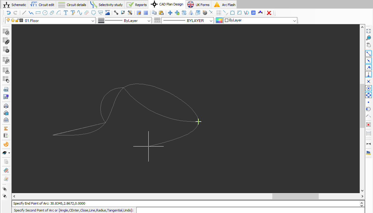
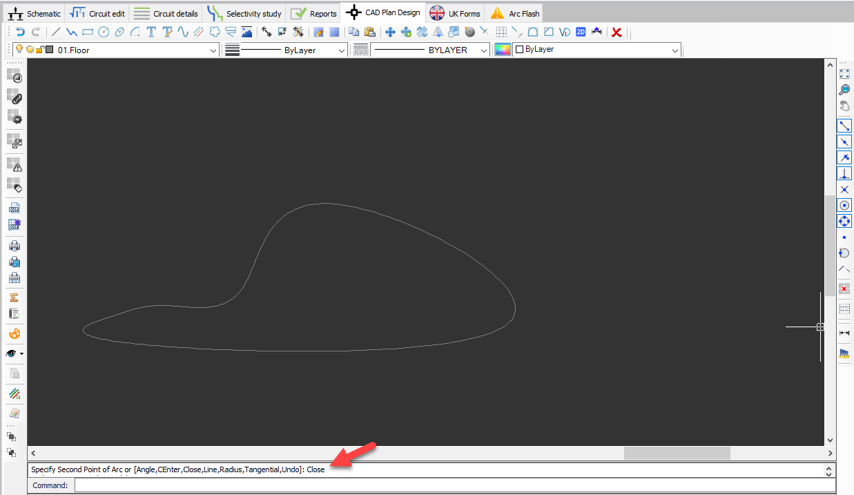
- Draw curved polyline: This button is used to draw a spline on the drawing area. This button will wait for a start point to be defined, first. Then, user will have various option to draw spine. Typing in desired options will expect user to define specific points. Once drawing of the spline is finished, user may like to leave the drawn shape as it is, or may choose to join the first and the last points by typing in Close.
- Draw multi-line: This button is used to draw a multi-line on the drawing area. For multiline settings, see Multiline Settings.
- Draw revision cloud: This button is used to draw a revision clouds on the drawing area.
- Draw leader: This button is used to draw a leader on the drawing area.
- Insert image: This button is used to insert an image on the drawing area.
- Draw dimension aligned: This button is use to insert a dimension aligned with the reference item.
- Draw dimension angular: This button is used to insert an angular dimension related with the reference item.
- Dimension styles: This buttons displays a windows to set dimension properties.
- Draw hatch: This button is used to draw a hatch.
- Figure hatch fill: This button displays a windows to set hatch properties.
- Clip copy: This button is used to copy selection.
- Clip paste: This button is used to paste already copied items on to the drawing area.
- Move: This button is used to move selected items.
- Copy: This button is used to copy and move selected items.
- Rotate. This button is used to rotate selected items.
- Mirror: This button is used to mirror selected items.
- Scale: This button is used to scale selected items.
- Explode: This button is used to explode selected items.
- Trim: This button is used to trim a selected item from a reference point.
- Array: This button is used to create an array from a selected item.
- Extend: This button is used to extend a selected item to a reference point.
- Fillet: This button is used to fillet the edges of two items.
- Chamfer: This button chamfers the edges of two items.
- Join: This button is used to join two items.
- Flatten: This button is used to flatten 3D items. In other words, it is used to convert 3D to 2D.
- Fix dimensions: This button will convert an external reference's dimensions from inches to metres.
- Erase: This button is used to delete selected items.