Pages Tab
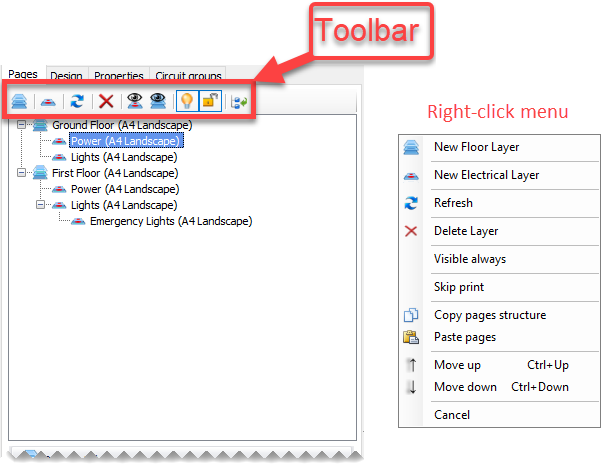
Top part of the Pages tab is reserved for layers. Toolbar located on top, and right-click menu will help users to create, edit, delete layers where related data will be shown in the white area below the toolbar.
Layers have a hierarchical order within the tree representation. Layers with the same level will hide others when they are selected. A sub-layer will appear on top of the parent layer.
For example, if First Floor layer is selected then, Ground Floor layer and all of its sub layers will not be displayed. If Power layer is selected under the Ground Floor layer, then contents of Power will be displayed together with Ground Floor layer. However, if Lights layer under the Ground Floor layer is selected, only contents of this layer will be displayed on top of Ground Floor layer contents.
Toolbar buttons and right-click menu items are , in order:
- Add background layer/New Floor Layer: This will add a layer which is not related with electrical design which may be a floor plan.
- Add electrical design layer/New Electrical Layer: This button will add a sub layer to the selected background layer where the user can draw electrical design components like wires, and insert symbols, etc.
- Refresh: This button will refresh the layers in case they do not appear correctly.
- Delete layer: This will delete the selected layer.
- Group Layers: This button will display a window where the user can select which layers to be visible when a layer is selected. The selection will override any default behaviour.
- Visible always: This option will set the selected layer to be visible all the time no mater which layer is selected.
- Skip print (Right-click menu only): This option will remove the selected layer form the report, Plan drawings of ElectrcialOM.
- Auto On/Off Layers: This button will help users to automatically turn unselected layers off. If the option is set to off, then, all the layers will be visible no matter which layer is selected.
- Auto Lock Layers: This button automatically locks unselected layers, where locked layers cannot be modified, if it is set to on mode. If this option is set to off, then, all the visible layers can me modified.
- Collapse nodes: This button will collapse nodes under selected layers only, other layers will not be affected.
- Copy pages structure/Paste pages: These will copy and paste selected layer.
- Move up/Move down (Right-click menu only): These options will move the selected layer up or down within the layers tree.
- Cancel (Right-click menu only): This will close the right-click menu.
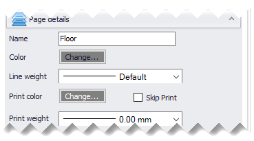
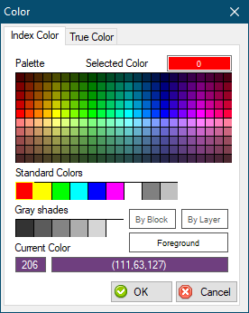
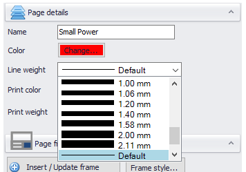
Middle section is reserved for layer properties where users may define a name, a colour, line weight, print colour and print line weight for the selected layer. Layer name can be typed into the text field next to Name, colour can be picked from the Colour window once clicked on Colour button, Line weight can be selected from the drop down list, also applicable to Print Colour and Print Line Weight.
Colour and Line weight settings are only used for display purposes, where Print colour and Print line weight is used for printing purposes. Skip print box can be used to exclude the selected layer from print and reports.
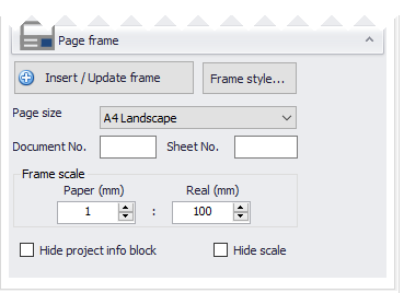
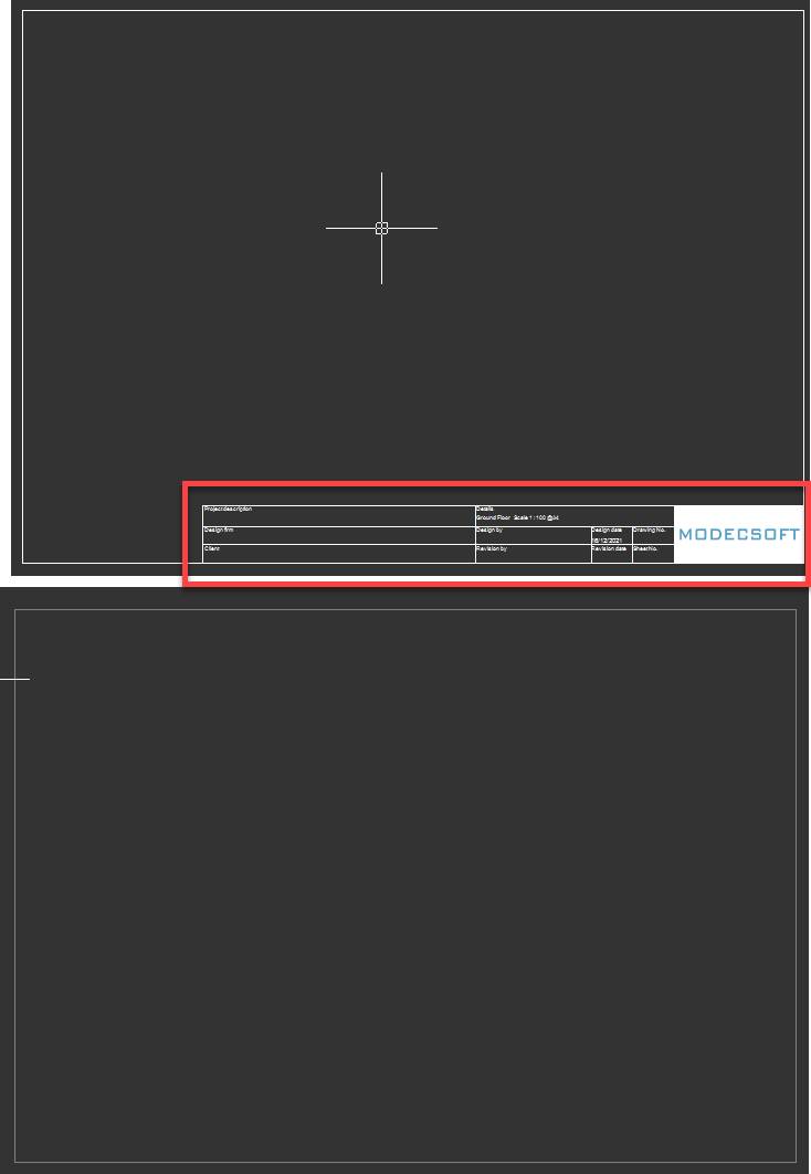
Bottom section is reserved for frame settings. Insert/Update frame button is used to insert a new frame to the selected layer. If there is a frame already inserted, then this button will update the frame to new settings. Any changes will only be reflected if Insert/Update frame button is pressed.
Frame style... button displays frames which can be used. ElectricalOM manual has more details regarding how to use the frame builder, please see Frame Builder Frame Builder.
Page size and layout can be selected using the drop down list below these buttons, and a document number and a sheet number can be define using the related text fields. Frame scale area is used to display the drawing scale on the frame, however, this can be removed by ticking the Hide scale box.
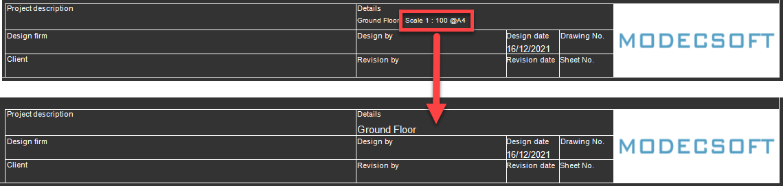
Hide project info block tick box will hide the title block completely and leave the frame only.