Creating a new symbol
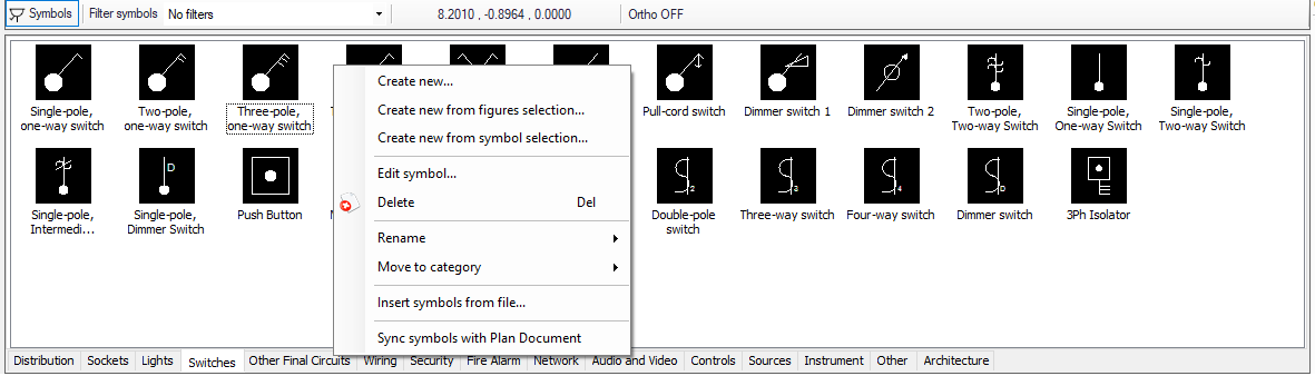
Crating a symbol may be done in three ways. A new symbol can be created from scratch, or using an existing symbol, or via drawing area. Following three chapters will cover these three ways in detail.
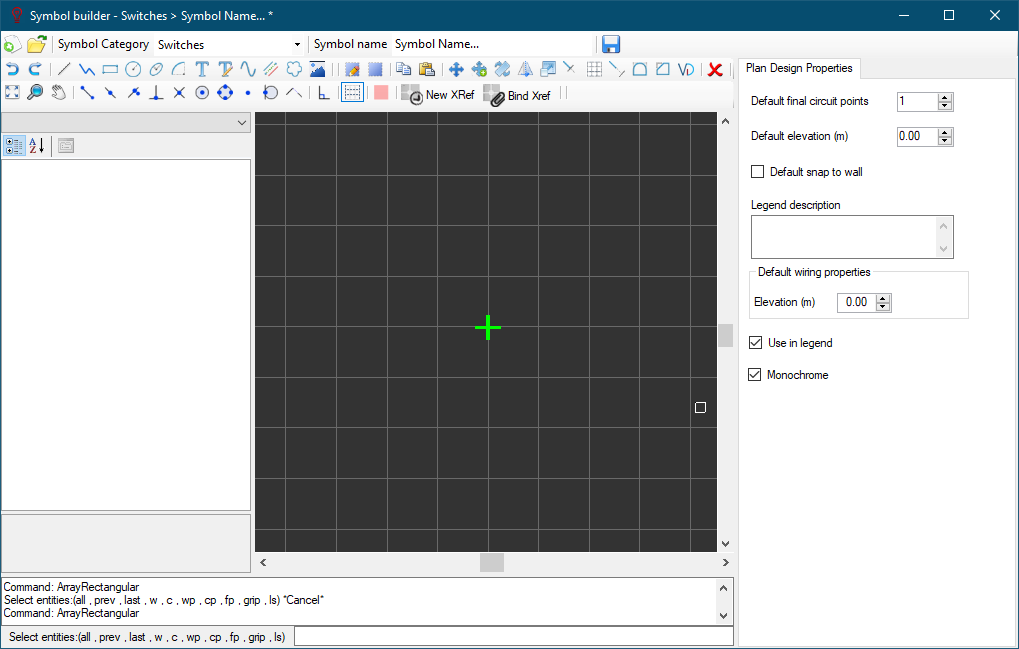
As a note, the Symbol Builder is the main tool we use to create or edit symbols throughout the ElectricalOM package and the usage is the same. Further details about this can be found in our Online Manual for ElectricalOM, Creating and Editing a Symbol - Symbol Builder section. and it will not be discussed here any further. However, there are a few additional options while using it via CAD Plan module, which are identified below.
- Default final circuit points: This option will tell ElectricalOM how many final circuits the created symbol will represent. This will be used while generating reports regarding quantities. However, it should also be noted that ElectricalOM will count the number of final circuits only if the symbol is under correct category. For example, if the symbol is created under switches, then, ElectricalOM will not include the number of final circuits to quantities; on the other hand, if the symbol is created under a final circuit category, let us say sockets, this time number of final circuits will be included.
- Default elevation (m): This will define the default height of the created symbol referenced to Z=0. This is used in cable length calculations and 3D representation.
- Default snap to grid: This is set snap-to-grip feature to default, so when the created symbol is inserted this option will be enabled.
- Monochrome: If this box is ticked then the symbol will be inserted as a monochrome symbol even if it is set to a certain colour.