Create Circuits via CAD Plan Design
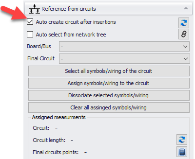
Circuits can be created via CAD Plan Design module, however, this is not as flexible as creating circuits via ElectricalOM core software. In order to create circuits, Auto create circuit after insertions box must be ticked.
Once the symbol(s) are placed and right-click performed to finalise placement, ElectricalOM will display Insert circuit window. Using this window, user may define the circuit's Prefix, Description, Circuit kind, power per insertion point, and supply point. Way list will display available ways of the selected board, if there is no available way, ElectrciaOM will display a warning and will not create the circuit.
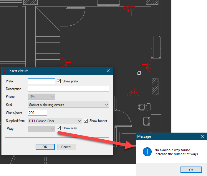
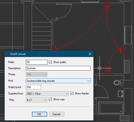
Using boxes next to the options, it is also possible to display or hide these parameters on CAD Plan Design drawing.
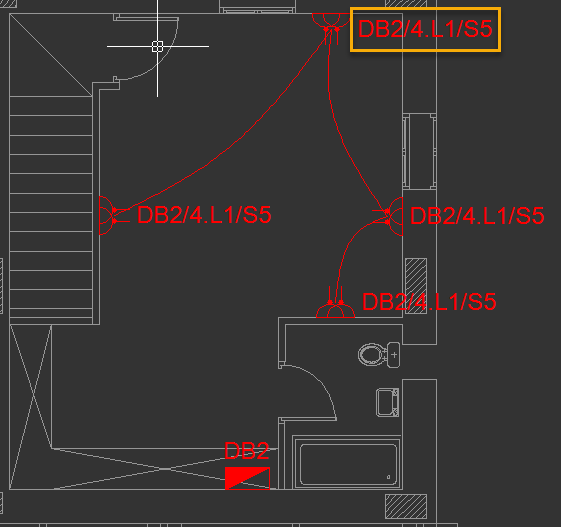
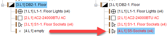
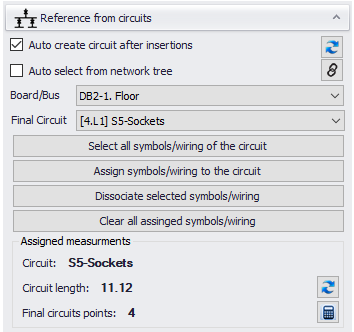
Once OK button is clicked, CAD Plan Design will create a circuit at ElectricalOM's network tree and assign the symbols to this newly created circuit also. However, user must revisit the circuit via ElectricalOM to revise circuit components like protection devices, cable cross-sections, etc.