Circuit Groups Tab
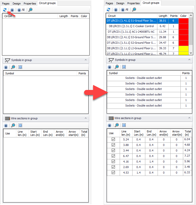
Circuit Groups Tab is used to visualise the circuits on the plan drawing and make some changes. It may be empty at first but CAD Plan Design will populate the tab with related data once the user clicks on Refresh Groups button.
The tab is divided into three sections and there are some buttons at the toolbars area. These are:

- Refresh groups button, see above.
- Apply measurement button applies any changes made within the related section only to the CAD Plan Design data, and updates ElectricalOM accordingly.
- Apply to all button applies all the changes regardless of section, and updates ElectricalOM accordingly.
- Zoom to selected will zoom to the selected item at the drain area.
- Select all will select all items from the related list.
It is important to notice that without using Apply buttons any changes made will be limited with CAD Plan Design and nothing will be reflected to ElectricalOM schematics.
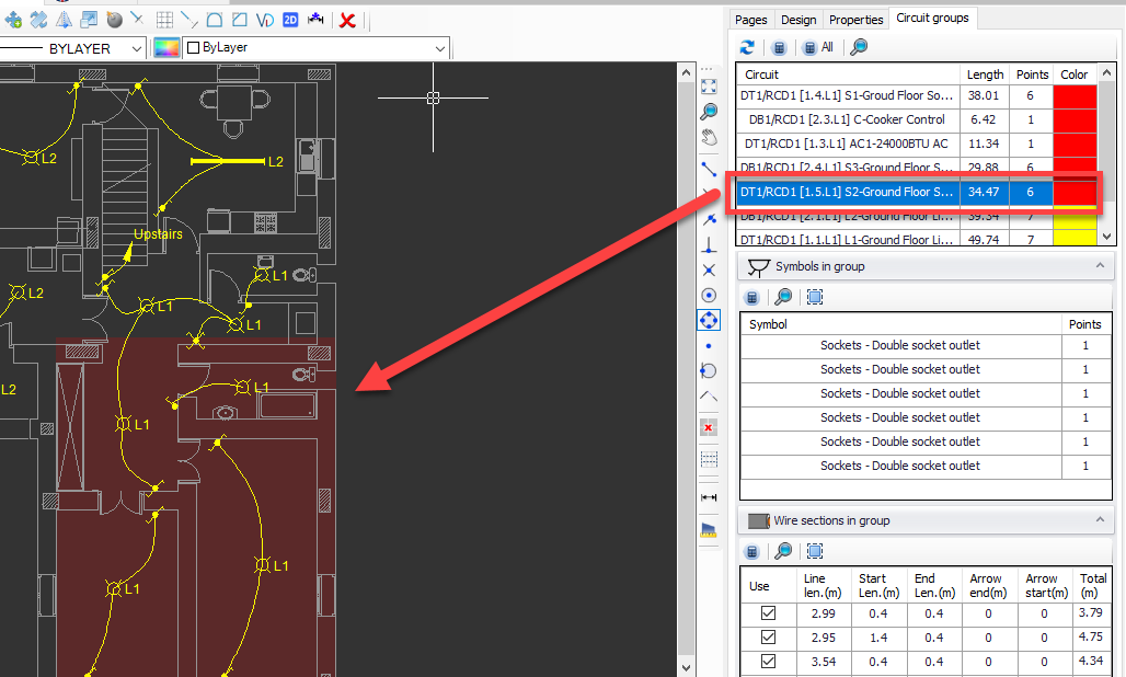
First section, located at the top, displays all the circuits which are assigned to symbols with their total wiring lengths, number of insertion points, and area colours. Area colours are used to show highlight he region of the circuit on the plan drawing. The colour is the same as the layer colour by default but it can be changed by clicking on it. When a circuit is selected, CAD Plan Design will highlight the circuit region on the plan drawing at the drawing area.
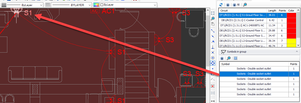
Middle section, Symbols in group, provides information about the symbols used with the selected circuit. If a symbol is selected, CAD Plan Design will highlight this symbol at the drawing area.
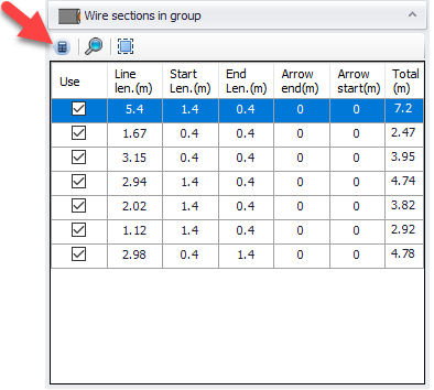
Last section, Wire section in group, provides wiring information for the selected circuit. The Starting Length, Ending Length, Arrow End Length, and Arrow Start Length fields can be clicked and modified by typing in any value, see Properties tab for details. Also, the use tick box can be used to include or exclude the related wiring from the length calculations, same as Exclude from measurements option at Properties Tab.