Creating New Symbols
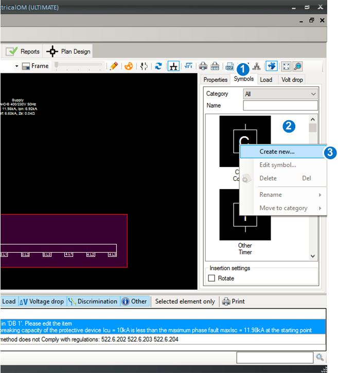
To create a new symbol, select the symbols tab (1) at the right panel of the schematic module. Then Right-click the symbols area list-box (2). Select Create new... (3) to open the symbol builder.
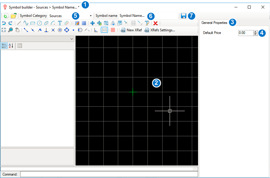
Using the symbol builder, you are able to create a symbol simply by drawing figures in the design area (2). The green cross indicates the insertion point of the symbol. The insertion point can be moved to a location of your choice.
From the general properties (3) you can set the default price (4) of the symbol, which is used in the Bill of Quantities Report. Each symbol can be placed in one of the categories (5), including Sources, Distribution Circuits, final circuits etc. A symbol name must be given (6) before saving (7).
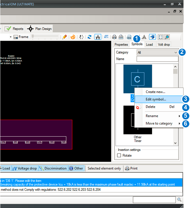
To edit an existing symbol, select the symbols tab (1) at the right panel of the schematic module. You may filter the symbols appearing by selecting a category (2). To edit a symbol, right-click it and then choose Edit symbol...(3) to enter the symbol builder. You can also delete (4), rename (5) or move the symbol to another category (6).