Solar Photovoltaic Systems (PVs) Modelling
To model Solar Photovoltaic Systems (PVs) in ElectricalOM, the user must connect a 3-Ph+N or 3Ph+N Solar PV Inverter component to a distribution node (e.g. distribution board, switchboard, junction box).
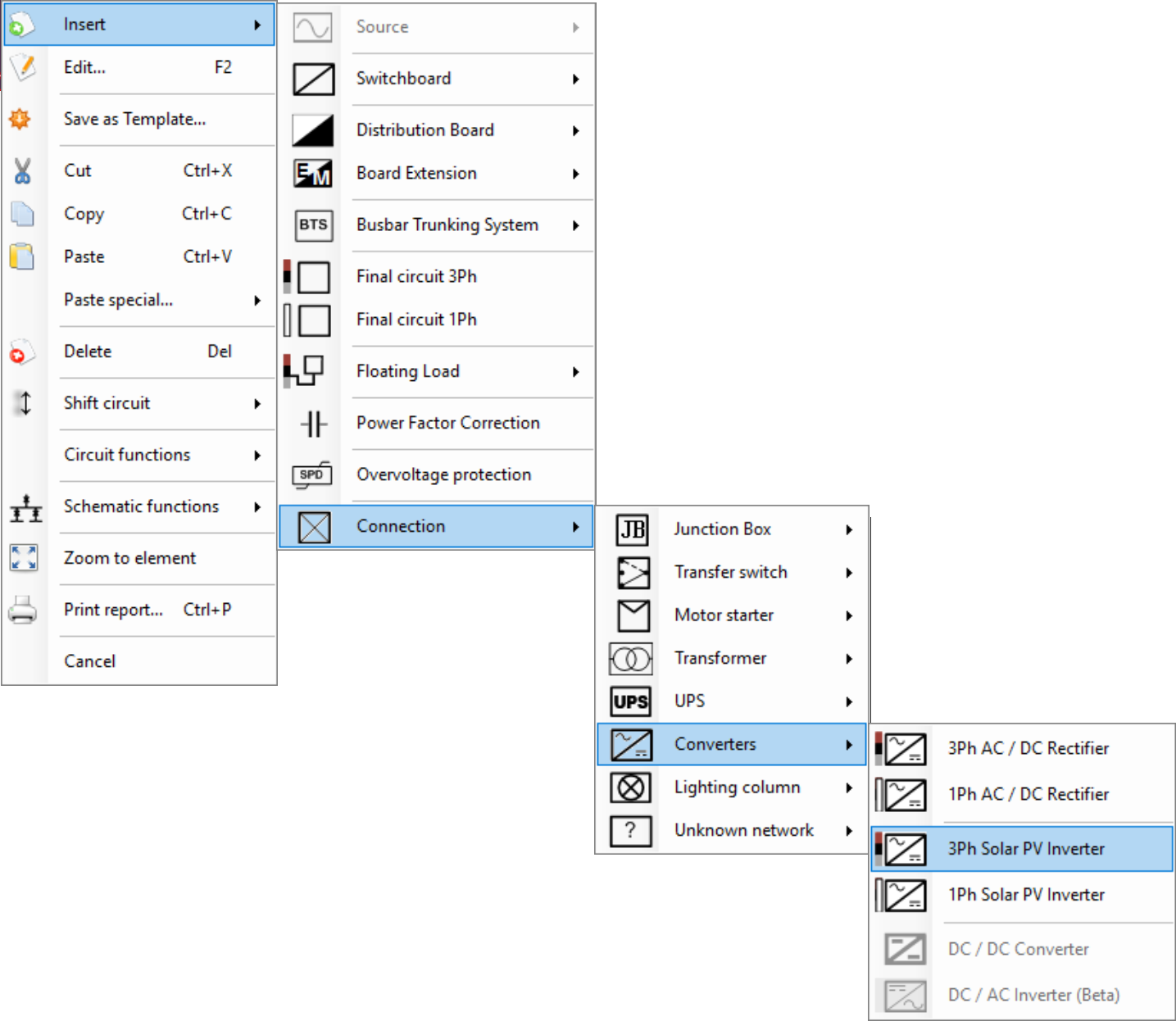
Figure 1 Inserting a Solar PV Inverter via the Actions Menu
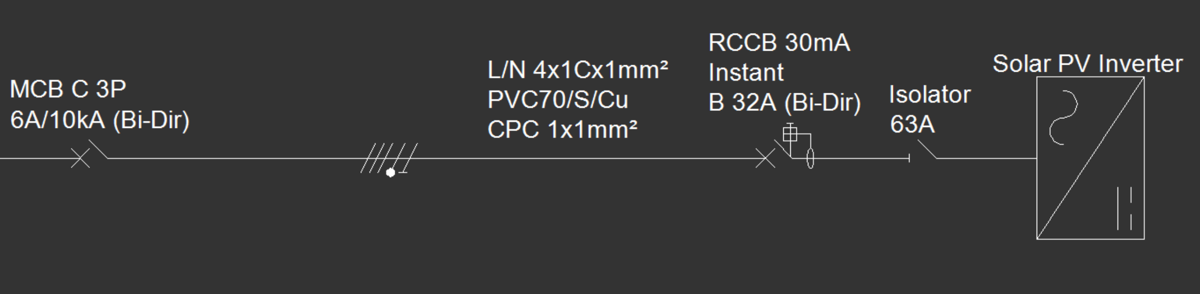
Figure 2 Single-Line Diagram (SLD) of the AC Side of a Solar PV Inverter
The Circuit Edit tab of a Solar PV Inverter component features the Inverter Settings section, where users can define various parameters related to the Solar PV Inverter.
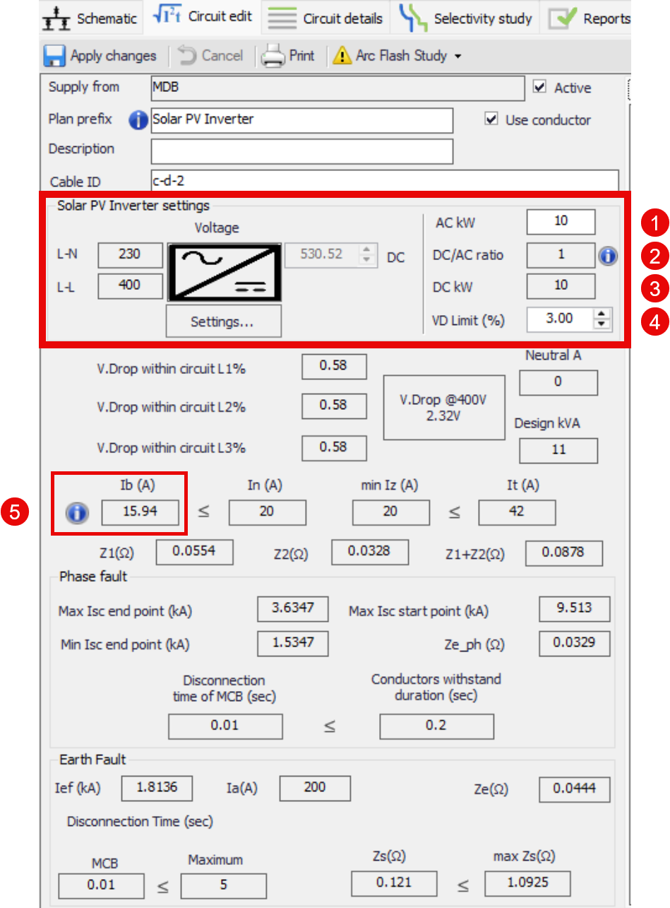
Figure 3 Solar PV Inverter Settings in the Circuit Edit Menu
The inverter's settings section enables the user to define key operational parameters for integrating solar PV inverters. These settings influence current calculations, protection coordination, and voltage drop compliance:
- AC kW – Specifies the inverter’s nominal output power on the AC side. This value is used to calculate the inverter's design current (Ib) and supports the sizing of AC cables and protection devices.
- DC/AC Ratio – This ratio defines the relationship between the installed PV array's DC capacity and the inverter’s AC output. This parameter helps simulate realistic operating conditions and assess potential inverter clipping or overloading.
- DC kW – Represents the total DC power of the connected PV array. It is automatically calculated based on the DC capacity.
- VD Limit (%) – Sets the maximum allowable voltage drop on the DC side of the inverter.
- Ib (A) – Indicates the calculated design current on the AC side of the inverter. It serves as a reference for selecting protective devices and ensuring that cable current-carrying capacities (Iz) are suitable, in accordance with regulatory standards.