Solar PV Inverter Settings - Power Optimiser Settings
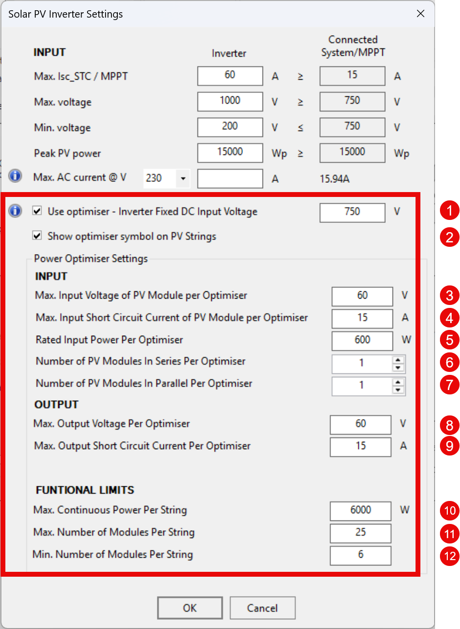
Figure 8 Solar PV Inverter Settings – Power Optimiser Configuration
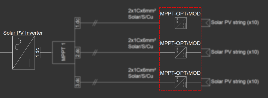
Figure 9 SLD of a Solar PV System with Power Optimisers
When optimisers are enabled, ElectricalOM performs checks against the following parameters to ensure that each PV string and module configuration remains within safe and manufacturer-specified operational limits:
- Use optimiser – Inverter Fixed DC Input Voltage: Enables optimiser mode and sets the inverter’s fixed DC input voltage when optimisers regulate the string voltage.
- Show optimiser symbol on PV Strings: Displays the optimiser icon on each string in the schematic to visually indicate the use of optimisers.
- Max. Input Voltage of PV Module per Optimiser (V): Sets the highest voltage a PV module can deliver to an optimiser without exceeding its input tolerance.
- Max. Input Short Circuit Current of PV Module per Optimiser (A): Defines the maximum current an optimiser can accept from a PV module under short-circuit conditions.
- Rated Input Power per Optimiser (W): Specifies the maximum continuous DC power each optimiser is designed to handle safely.
- Number of PV Modules in Series per Optimiser: Determines the maximum number of PV modules that can be connected in series to a single optimiser.
- Number of PV Modules in Parallel per Optimiser: Determines the maximum number of PV modules that can be connected in parallel to a single optimiser.
- Max. Output Voltage per Optimiser (V): Sets the maximum DC voltage an optimiser can output to the string.
- Max. Output Short Circuit Current per Optimiser (A): Indicates the highest output current the optimiser can deliver during a short-circuit event.
- Max. Continuous Power per String (W): Limits the total DC power a single string (with optimisers) can output continuously.
- Max. Number of Modules per String: Sets the maximum number of PV modules allowed in a string using optimisers.
- Min. Number of Modules per String: Sets the minimum number of PV modules required in a string using optimisers to maintain correct voltage and operation.
Info Icon (ℹ️)
Use optimiser – Inverter Fixed DC Input Voltage (Point 1)
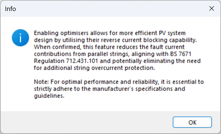
Figure 40 Info Icon – Optimiser Reverse Current Blocking and Overcurrent Protection Compliance