Recent Posts

Pages: 1 ... 8 9 [10]
91
ElectricalOM for Advanced Users / Re: Parallel Battery Configuration
« Last post by Mert on 05 October 2021, 13:49 »
To achieve this you need to have the battery selected and then go to main menu Functions --> Parallel source operation and check the other Battery. Now the two switches will be set to close.
92
ElectricalOM for Advanced Users / Parallel Battery Configuration
« Last post by RCDGuy on 05 October 2021, 13:48 »
I am using two battery DC sources connected in parallel each source having its own output fuse. Both batteries are in hard parallel at the distribution board input via switches.

The battery fuse discriminates with the down stream load MCBs (Inverter loads) but i am getting a critical error due to the total loading being applied to only one (active battery source. Is it possible to have both battery sources connected to the distribution/switchboard at the same time as this is how it would function in reality?

93
ElectricalOM for New Users / Re: Exporting To Easycert
« Last post by Mert on 05 October 2021, 13:44 »
To import the exported eom2ec file:
1. Open tysoft easycert and create a new certificate
2. Go to DB schedule and right click on the circuits area
3. Select import
4. Choose the exported file eom2ec file
94
ElectricalOM for New Users / Exporting To Easycert
« Last post by RCDGuy on 05 October 2021, 13:44 »
Hi, I have exported a project to use in Tysoft Easycert using the export options in the file menu.
This produces a file that is not recognized by the Easycert application and it will not import it.
Are there settings that need to be adjusted?
95
Calculations & Checks / Re: Max Earth Fault Loop Impedance figures
« Last post by Mert on 05 October 2021, 13:41 »
This is actually correct, considering the RCD will be responsible to protect during the earth fault conditions. The maths are:

MaxZs =( Cmin x Uo ) / Ia

For a 30mA RCD Ia = 30mA ==> MaxZs = (0.95x230)/0.03 = 7283.3 Ohms

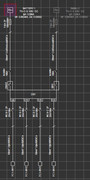
Now in case, you want the overcurrent device to be responsible for the protection (recommended for TN systems) you need to check the relevant option in the circuit editor. See the attached image 1.

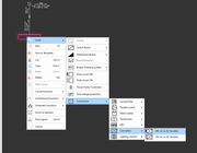
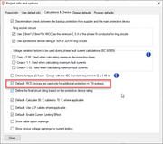
You can have this as the default behaviour for your circuits by setting it at the project option defaults (main menu-->Edit-->Project info and options). See the attached image 2.

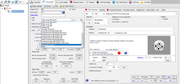
In your current project, you can multi-select and apply this setting from the circuit details page. See the attached image 3.


96
Calculations & Checks / Max Earth Fault Loop Impedance figures
« Last post by RCDGuy on 05 October 2021, 13:39 »
I have been going through the EICR that i am carrying out and have noticed some discrepancies from the BS7671 and your list . For example 61009 C 32 30ma - 7283.33 Zs in the regs 0.68 Zs on 0.4 secs, also 60898 D 63 - 0.65 in the regs 0.35 Zs on 5 secs. Can you clarify that they are correct please.
97
CAD Plan Design / Re: Uploading DWG to CAD Plan Design
« Last post by Mert on 05 October 2021, 13:35 »
In case your XREF appears on the XREF settings but you can not see it in the CAD Plan environment, I suggest you to use the Fix XREFs function which is below the XREF settings (indicated with a warning icon). This normally happens when accidentally the location of your XREFs changes.

In addition, I would like to let you know that this might be a compatibility issue with earlier versions of dwg AutoCAD files. Instead, try to save your dwg drawings in an earlier AutoCAD version (e.g. 2013) using AutoCAD or the free Autodesk software, DWG TrueView.
98
CAD Plan Design / Uploading DWG to CAD Plan Design
« Last post by RCDGuy on 05 October 2021, 13:35 »
I am struggling to retrieve a dwg using the New XRef i have clicked on this and clicked on a drawing but unable to see it on the screen, but it shows up when you click on Xref settings it shows it there.
Is there different types of DWG.?
99
Hello,

To model renewable systems in the software, you can use one of the following methods.

1) You can insert a 3ph/1ph final circuit and change the load kind to a renewable source (from the load kind drop down menu in the circuit editor). This allows you to model the AC side of any renewable system (e.g. PV System, Wind Turbine) for simple cable calculations. The KVA/load rating of the renewable source will not contribute to the total connected load of its supply panel as this generates energy.
2) You can insert a 3ph/1ph AC-to-DC Converter (select Insert, Connection and then Converters) to model the AC and DC side of a Solar Photovoltaic Inverter (you can also specify the characteristics of the Inverter such as its rating, fault current, DC voltage and voltage drop).

Please see the images attached.


100
How do I integrate a PV or wind system into my design?

I cannot see a solution in the FAQ's
Pages: 1 ... 8 9 [10]