Voltage Drop Calculation
Voltage Drop Calculation
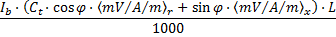
For single phase circuits:
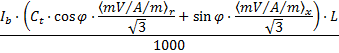
For three phase circuits:
With:
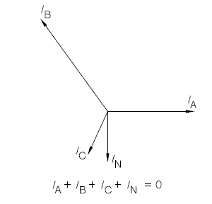
Note: For unbalanced 3 phase circuits, current will be flowing in the neutral conductor as illustrated in the phasor diagram below. The voltage drop in each phase is calculated by summing of the vectors of the phase and the neutral voltage drops.
|
Voltage Drop Limits Check The software checks that the total voltage drop (between the origin of the installation and the circuit) is in the voltage drop limit set. The voltage drop limits can be user defined or according to Table 4Ab in Appendix 4 of BS7671:2018.
|