Minimum Phase Fault Current Calculation
Minimum Phase Fault Current Calculation
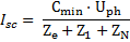
The type of the circuit will determine how the minimum phase fault current will be calculated. It is done according to IET Electrical Guidance Note 1, using the factors in Table E2 to calculate the maximum impedance of the conductor. Single phase circuits:
Three phase and Neutral circuits:
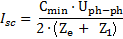
Three phase (without neutral) circuits:
With:
|
Adiabatic Check of the Phase Conductor During Phase Fault The Software acts according to regulation (434.5.2), in order make the adiabatic check i.e whether or not the heat energy
With:
The software compares the maximum permissible disconnection time with the time taken from the time-current curve of the protective device at the phase fault to find if the adiabatic check stands. Note: For disconnection times less than 0.1 sec, the software checks for available Let‐Through energy characteristics of the protective device at the calculated fault current and uses them during the adiabatic check. |