Earth Fault Current Calculation

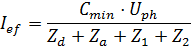
ΤΤ Earthing System:
With:

|
the phase to neutral voltage
|

|
the impedance of the supply
|

|
the impedance of the earthing electrode
|

|
the impedance of the phase conductor
|

|
the impedance of the CPC
|

|
The voltage factor Cmin is to take into account the worst case voltage variations conditions in a low voltage installation, specified in IEC 60909 as 0.95
|
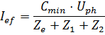
ΤN Earthing Systems:
With:

|
the phase to neutral voltage
|

|
the exterior impedance
|

|
the impedance of the phase conductor
|

|
the impedance of the protective CPC
|

|
The voltage factor Cmin is to take into account the worst case voltage variations conditions in a low voltage installation, specified in IEC 60909 as 0.95
|
|
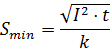
Adiabatic Check of the Protective Conductor During Earth Fault
The software, in accordance with regulation (543.1.3), makes use of the earth fault current, together with the operating time that has been found from the time-current curve of the protective device, in order to obtain a lower bound on the cross-sectional area of the protective conductor (CPC):
With:

|
the minimum cross-sectional area of the protective conductor in mm2
|

|
the cable factor
|
If the operating time is less than 0.1 sec, then

|
Is the let-through energy characteristic of the protective device
|
Otherwise,

|
is the earth fault current
|

|
is the operating time taken from the time-current curve of the protective device
|
Note: If the protective device is an RCD or RCCB, then the software makes the check using for t the operating time of the RCD or RCCB.
Note: Impedances under fault conditions are calculated in accordance with Guidance Note 1: Table E2.
|